Shell and Tube Heat Exchangers: Calculations
The basic design calculation for any heat exchanger is the determination of heat transfer area. Most generally, this is done using

although in practice it is more common to assume that fluid properties can be treated as constant at the bulk average values, and approximate the design equation with:
To use this equation, it is necessary to determine the heat transfer coefficient and the temperature difference. We have seen that for a double pipe heat exchanger the required average temperature difference is the log mean temperature difference (LMTD). Unfortunately, the flow patterns in shell and tube exchangers are such that the LMTD by itself is no longer adequate. It must first be adjusted by means of a correction factor.
The second parameter that must be calculated for a typical process design is the pressure drop in the fluids moving through the exchanger.
Correcting the LMTD
The LMTD was developed for a model restricted to parallel and countercurrent flow patterns. In shell and tube exchangers, the flow pattern is a mixture of cocurrent, countercurrent, and crossflow, so the LMTD does not directly apply. Instead, a corrected LMTD must be used. Correction factors (F correction factors) are tabulated and used to adjust:

The correction factor charts are available from many sources (Levenspiel Fig 13.5-10; Brodkey & Hershey Fig 11.16; MSH6 Fig 15.6). They are based on two parameters:

These parameters are cross-referenced on the appropriate chart to find the F factor. A different chart is needed for each exchanger layout (1- 2, 1-4, etc.). Note that the charts provided in MSH are written using hot and cold subscripts and assume that the hot fluid is on the shell side of the exchanger. Be careful and do what is right for your problem.
F factor curves drop off rapidly below 0.8. Consequently, if your design is indicating an F less than 0.8, you probably need to redesign (add tube passes, increase temperature differences, etc.) to get a better approximation of countercurrent flow and thus higher F values.
Similar correction factors are available for exchanger types other than shell and tube, including crossflow and compact exchangers.
Tube Side Heat Transfer Coefficients
Tube side heat transfer coefficients are easy to determine, since the Seider-Tate equation (or equivalent) applies. The most common slipup made at this stage is to incorrectly divide the stream flow among the tubes. Be sure to adjust all flowrates and velocities for the number of tubes AND the number of tube passes. If an exchanger has 200 tubes in 2 passes, the total flow will be moving through 100 tubes at a time; if there are 4 passes, it will go through 50 tubes.
Tube Side Pressure Drop
Tube side pressure drop is calculated using the same pipe flow factors developed in your fluid mechanics class. Again, be careful to divide the total flow among the correct number of tubes. The isothermal friction factor can be obtained from the Moody/Stanton charts or an appropriate correlation.
This friction factor must be corrected for the effect of temperature on viscosity. MSH6 pp. 11516 explains correction factors, but you can probably get good enough results using the SeiderTate viscosity correction:

This can then be used with the mechanical energy balance to get the pressure drop:

Shell Side Heat Transfer Coefficients
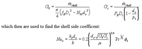
Shell side heat transfer coefficients cannot be obtained from Seider- Tate, etc., since the flow patterns and many other factors don't match. For this class, you should use the Donohue correlations (MSH6 eq. 15.3- 6). This requires calculation of several values -- notably Gb, the mass velocity of the shell side fluid if it was all moving parallel to the tubes, and Gc, the mass velocity if all the fluid was moving across the tubes.
To get these, you will need several other numbers:
- Ds, the shell inside diameter
- fB, the fraction of the shell cross-section that makes up the baffle window
- Nbt, the number of tubes in the baffle window (usually approximated by fb*Ntubes)
- PB, the baffle pitch (spacing)
- pt, the tube pitch
- do, the tube outside diameter
With these, the required mass velocities become

with properties based on the shell side bulk temperature. Remember that the flow is outside the tubes, so the wall temperature correction is based on the outside wall temperature.
Shell Side Pressure Drop
The shell side flow path is considerably more complex than for a tube, so the calculation of shell side pressure drop is significantly more complicated as well. For our purposes, we will use a correlation presented by Kern. It is somewhat dated, but has the advantage of mirroring the tubeside calculation.
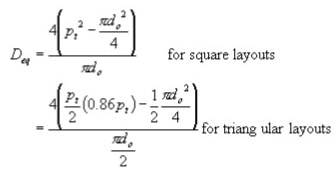
Begin by determining a shell side equivalent diameter, Deq. This will depend on the tube layout, since the arrangement effects both the flow area and perimeter

(You may recognize the 0.86 in the triangular layout expression as the sine of a 60 degree angle.)
This shellside equivalent diameter is combined with the crossflow mass velocity to obtain a Reynolds number

which can be taken to an appropriate chart (such as p. 839 of Kern) and used to get a friction factor. Note that the chart provides a dimensional friction factor (unlike the dimensionless values used for pipe flow).
To transform the friction factor to a pressure drop, we need a count of how many times the fluid crosses the tube bundle. It crosses between the baffles, so the "crosses" will be one more than the number of baffles, NB. If the number of baffles isn't already known, it can be determined using the baffle spacing:

The pressure drop is then determined using the equivalent diameter, crossflow velocity, friction factor, number of crosses, and fluid properties:

References:
- Brodkey, R.S. and H.C. Hershey, Transport Phenomena: A Unified Approach, McGrawHill, 1988, pp. 539-43.
- Kern, D.Q., Process Heat Transfer, McGraw-Hill, 1950, pp. 136-39, 147-48.
- Levenspiel, O., Engineering Flow and Heat Exchange, Revised Edition, Plenum Press, 1998, pp. 257-65.
- McCabe, W.L., J.C. Smith, and P. Harriott, Unit Operations of Chemical Engineering (5th Edition), McGraw-Hill, 1993, pp. 359-62, 428-39.
- McCabe, W.L., J.C. Smith, and P. Harriott, Unit Operations of Chemical Engineering (6th Edition), McGraw-Hill, 2001, pp. 362-65.
- Mehra, D.K., "Shell-and-Tube Heat Exchangers", Chemical Engineering, July 25, 1983, pp. 47-56.
- Standards of Tubular Exchangers Manufacturer's Association, 6th Edition, 1978, pp. 24, 26, 144, 146.

