
And the torque dueapplying kirchhoffs loop rule
| U | = | 1 | Li 2 | = | 1 | L | | V | | |
|---|---|---|---|---|---|---|---|---|---|---|
| L | 2 | 0 | 2 | | r | |
∴Fraction of energy lost across inductor as heat
1800,
Example 3: A coil of area 2 m2 is placed in magnetic fieldwhich varies as B = ( 2t 2 + 2 ) T with area vector in the direction of B. What is the magnitudeof E.M.F.at t=2s?
| E | = − | d | φ | |
|---|---|---|---|---|
| dt | ||||
We want to find E.M.F. through the coil when
t=2 s. If we find the rate of change of flux, we have E.M.F.
| φ = f | BScos180 0 |
|
2 | × | 20 10 | −4 |
|
⇒ | E | = | A. | dB | = | A 4t ( | + | 4 | ) | | E | | = | d Φ B | |||||
|---|---|---|---|---|---|---|---|---|---|---|---|---|---|---|---|---|---|---|---|---|---|---|---|---|---|
| dt |
|
dt |
|
||||||||||||||||||||||
| Therefore, change in flux, −3 | |||||||||||||||||||||||||
| for A | = | 2; | + | ||||||||||||||||||||||
| 8.0 10 | −3 | ||||||||||||||||||||||||
|
|||||||||||||||||||||||||
|
|||||||||||||||||
|---|---|---|---|---|---|---|---|---|---|---|---|---|---|---|---|---|---|
|
L | = | |||||||||||||||
|
|||||||||||||||||
| U L | = | 1 | |||||||||||||||
1m |
2 | ||||||||||||||||
|
|||||||||||||||||
| 2U | = | 2 | × | 3.6 | × | 10 | 6 | = | |||||||||
| i 2 | ( | 200 ) | |||||||||||||||
The arrangement is shown in Figure. The field due to straight wire at the center of loop is:
| φ = | BA | = | B | × π r | 2 | = | 2I 10 | −7 | × π× | ( 10 | −3 |
|---|
Example 6: The two rails of a railway track insulated from each other and the ground are connected to a millivolt-meter. What is the reading of the voltmeter when a train travels at a speed of 108 kmh-1 along the track? Given the vertical component of earth’s magnetic field = 2×10⁻⁴ T& separation between the rails= 1m.
Sol: Here the train can be considered to move perpendicular to the earth’s magnetic field. Due to motion of the train, motional e.m.f. is induced in the
|
E | = − |
|
, | ... (i) | |||||||||||||||||||||||||||||||||||||||
|---|---|---|---|---|---|---|---|---|---|---|---|---|---|---|---|---|---|---|---|---|---|---|---|---|---|---|---|---|---|---|---|---|---|---|---|---|---|---|---|---|---|---|---|---|
| e | = | d φ | = | 2 | π× | 10 | −13 | |||||||||||||||||||||||||||||||||||||
| dt | As (v | |
θ = | 0 o |
|
... (ii) | ||||||||||||||||||||||||||||||||||||||
| | I | = | ( | 3 | + | 2t | ) | × |
|
∴ | E | |||||||||||||||||||||||||||||||||
| 2 | × | |||||||||||||||||||||||||||||||||||||||||||
| So, | dI | = | 2 10 | −2 | As |
|
||||||||||||||||||||||||||||||||||||||
| & | v | = | 180 1000 | = | 50ms |
|
||||||||||||||||||||||||||||||||||||||
| dt | ... (iii) | |||||||||||||||||||||||||||||||||||||||||||
| And hence, | e | = | 2 | π× | 10 | −13 | × | 2 10 | −2 | = | 1.26 10 | −14 | 60 | × | ||||||||||||||||||||||||||||||
| E | = | 2 10 | −4 | × ×1 50 | = | 10 10 | −3 |
|---|
Example 7: A very small circular loop of area 5 cm2 &resistance 2 Ω, and negligible inductance is initially coplanar and concentric, with a much larger fixed circular loop of radius 10cm. A constant current of 1
| I A | a | � |
|
- | I |
|
|---|
(a) The Figure represents the arrangement of coils. When current passes through the larger loop, the field at the center of larger loop is,
| B | = | µ | 0 | I | = | µ | 0 | 2 | π× | I | = | 10 | −7 | × | 2 | π× | 1 | = | 2 | π× | 10 | −6 | Wb |
|---|---|---|---|---|---|---|---|---|---|---|---|---|---|---|---|---|---|---|---|---|---|---|---|
| 1 | 2R | 4 | π | R | 0.1 | m 2 | |||||||||||||||||
is normal to the area of smaller loop.
The total power dissipated in the circuit if E is the E.M.F. linked with the coil is
| The flux linked with the smaller loop at time t, | E | × = | P | = | P 1 | + | ) | = | |||||||||||||||||||||||||||||||||||||||||||
|---|---|---|---|---|---|---|---|---|---|---|---|---|---|---|---|---|---|---|---|---|---|---|---|---|---|---|---|---|---|---|---|---|---|---|---|---|---|---|---|---|---|---|---|---|---|---|---|---|---|---|---|
| φ = 2 | B S cos 1 2 | θ = | ( | 2 | π× | 10 | −6 | )( 5 10 | −4 | ) | |||||||||||||||||||||||||||||||||||||||||
| ⇒ | E | = | ( | ||||||||||||||||||||||||||||||||||||||||||||||||
| 0.76 | + | 1.20 | |||||||||||||||||||||||||||||||||||||||||||||||||
| ( | 9.8 / 3 | ||||||||||||||||||||||||||||||||||||||||||||||||||
| i.e., | φ = π×2 | 10 | −9 |
|
|||||||||||||||||||||||||||||||||||||||||||||||
| The E.M.F. E=l•BvT | ∴ | v | = | E | = | 0.6 | = | 1 ms |
|
||||||||||||||||||||||||||||||||||||||||||
| T | Bl | 0.6 | × | 1 | |||||||||||||||||||||||||||||||||||||||||||||||
| E 2 | = − | d | φ 2 | = − | d | ( | π× | 10 | −9 | cos | ω t | = | V | 2 | V |
|
|||||||||||||||||||||||||||||||||||
| dt | dt | P | |||||||||||||||||||||||||||||||||||||||||||||||||
| R |
|
||||||||||||||||||||||||||||||||||||||||||||||||||
| i.e., E 2 | = π× | 10 | −9 | ω | |||||||||||||||||||||||||||||||||||||||||||||||
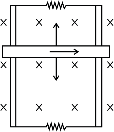
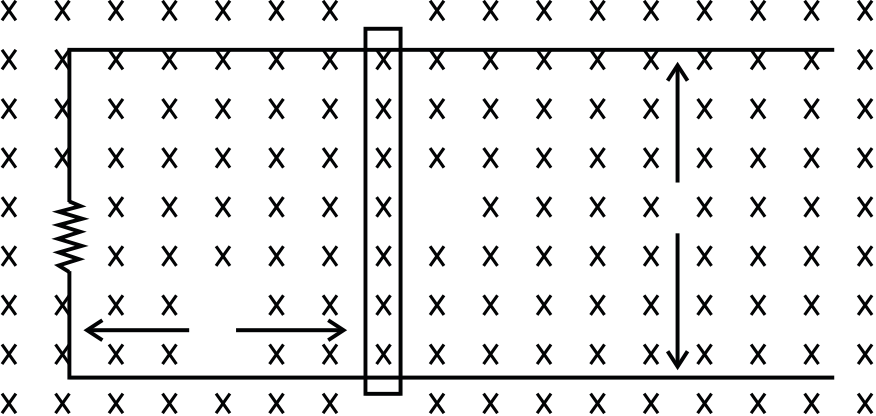
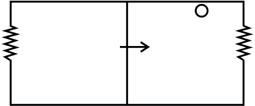
Example 8: Two parallel vertical metallic rails AB and CD are separated by 1 m. They are connected at the two ends by resistances R1 and R2 as shown in Figure 22.40. A horizontal metallic bar of mass 0.2 kg slides without friction, vertically down the rails under the action of gravity. There is a uniform horizontal magnetic field of 0.6 T perpendicular to the plane of the rails. It
| R | = | E 2 | = | ( | 0.6 | ) 2 |
= | 9 | Ω |
|
||
|---|---|---|---|---|---|---|---|---|---|---|---|---|
| 1 | P 1 | 0.76 | 19 | |||||||||
| R | 2 | = | E 2 | = | ( | 0.6 | = | 0.3 | Ω | |||
| P 2 | 1.20 | |||||||||||
22.30 | Electromagnetic Induction and Electromagnetic Waves
The network mesh ASCQ is a balanced Wheatstone. So there is no current through branch AC.
Let R be the effective resistance of mesh ASCQ
| ∴ | R | = | 6 | × | 6 | = | 3 | |
|---|---|---|---|---|---|---|---|---|
| 6 | + | 6 |
E = 2×0.1×V0 = 0.2V0
& using Ohm’s law the current in the circuit is
| I | = | 1 | × | I | = | 30 | = | 1.5 A | |||
|---|---|---|---|---|---|---|---|---|---|---|---|
| | s | 20 | P | 20 |
Example 11: An infinitesimally small bar magnet of dipole moment M is pointing and moving with the speed v in the x-direction. A small closed circular conducting loop of radius ‘a’ and of negligible self-inductance lies in the y-z plane with its center at x=0, and its axis coinciding with the x-axis. Find the force opposing the motion of the magnet, if the resistance of the loop is R. Assume that the distance x of the magnet from the center of the loop is much greater than a.
Sol: The flux linked with loop due to magnetic field of bar magnet will decrease as the bar moves away from the loop. The current induced in the loop will oppose its cause i.e. will create a magnetic field at the location of bar magnet such that the bar magnet is attracted towards the loop, thus bar magnet is decelerated.
| φ = | BA | = π a 2 | × | µ | 0 | 2M | ||
|---|---|---|---|---|---|---|---|---|
|
4 | π | x | 3 | ||||
Example 10: A power transformer is used to step up an alternating e.m.f. from 230 V to 4.6kV to transmit 6.9KW of power. If primary coil has 1000 turns, find
| ∴I | I = | n E |
du = | ce µ | urrent: 3 Ma 2 | ⋅ | v | = | 3 µ | 0 Ma 2 | ⋅ | |||||
|---|---|---|---|---|---|---|---|---|---|---|---|---|---|---|---|---|
| R | 2 | π | Rx |
|
2Rx |
|
||||||||||
moving in the external field it will be opposed by the force which is equal to heat dissipated in the coil due to resistive force.
Heat dissipated in coil= Resistive force acting on coil while it is in motion.
Example 12: In an L-C circuit L=3.3 H and C=840 pF. At t=0 charge on the capacitor is 105µC and maximum.
Compute the following quantities at t=2.0 ms:
|
||||||
|---|---|---|---|---|---|---|
| q 2 | ||||||
| 2C | ||||||
| × | 10−12 | |||||
The circuit when connected to AC supply, oscillated and the angular frequency of oscillations of circuit which is,
ω = 1 = 1 = 1.9×10 4 rad/s LC 3.3×840×10−12
∴ Energy stored in the capacitor is
| U | = | 1 | = | ( 105 | × | 10 | −6 |
|
= |
|
||||
|---|---|---|---|---|---|---|---|---|---|---|---|---|---|---|
| 2 C | 2 | × | 840 | × | 10 | −12 | ||||||||
Sol: The maximum force exerted by the wave is F=FE+FB= qE + qvB.
| = | (1.6 10 | −19 | )(300) | = | 4.8 10 | −17 | ||||||||||||||
|---|---|---|---|---|---|---|---|---|---|---|---|---|---|---|---|---|---|---|---|---|
| c | = |
|
E 0 | |||||||||||||||||
| B |
|
|||||||||||||||||||
| B 0 | = | |||||||||||||||||||
| B | = | 300 | = | 10 | −6 | |||||||||||||||
| 0 | 3.0 | × | 10 8 | |||||||||||||||||
∴ Maximum magnetic force FB= B0qv sin 90o=B0qv
Substituting the values we have,
JEE Advanced/Boards
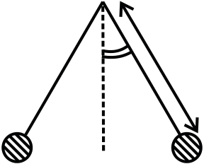
Example 1: A wire frame of area 3.92×10⁻⁴m and resistance 20Ω is suspended from a 0.392 m long thread. There is a uniform magnetic field of 0.784 T and the plane of wire-frame is perpendicular to the magnetic field. The frame is made to oscillate under gravity by displacing it through 2×10⁻²m from its initial position along the direction of magnetic field. The plane of the frame is always along the direction of the thread and does not rotate about it. What is the induced e.m.f. in a wire-frame as a function of time? Also find the maximum current in the frame.
Substituting the values, we get
(B) Find the equation of motion & its solution
|
A | M | ||||||||||||||||||||||||||||||||||||||||||||||||
|---|---|---|---|---|---|---|---|---|---|---|---|---|---|---|---|---|---|---|---|---|---|---|---|---|---|---|---|---|---|---|---|---|---|---|---|---|---|---|---|---|---|---|---|---|---|---|---|---|---|---|
| m | dx | 2 | = − | mgsin | θ | or | d x 2 | = −gsin | ||||||||||||||||||||||||||||||||||||||||||
| dt | 2 | dt | 2 | |||||||||||||||||||||||||||||||||||||||||||||||
| θ = | x | ⇒ | x |
|
||||||||||||||||||||||||||||||||||||||||||||||
| |
|
|||||||||||||||||||||||||||||||||||||||||||||||||
| | d x 2 | = − θ ⇒ | d 2 | θ | = − | g | θ | |||||||||||||||||||||||||||||||||||||||||||
| dt | 2 | dt | 2 |
|
||||||||||||||||||||||||||||||||||||||||||||||
| Putting | ω = | ( | g / l , ) | |||||||||||||||||||||||||||||||||||||||||||||||
| d 2 | … (ii) | |||||||||||||||||||||||||||||||||||||||||||||||||
| dt | ||||||||||||||||||||||||||||||||||||||||||||||||||
|
||||||||||||||||||||||||||||||||||||||||||||||||||
|
θ = θ 0sin | ω | ||||||||||||||||||||||||||||||||||||||||||||||||
| Substituting the value of θ in equation (i), we get | x | |||||||||||||||||||||||||||||||||||||||||||||||||
| E | = | BA | ( | θ 0 | sin t | ) | d | ( | θ | 0 | sin t | R3 | ||||||||||||||||||||||||||||||||||||||
| dt | R2 |
|
||||||||||||||||||||||||||||||||||||||||||||||||
| = | BA | θ 0 | sin t ω ωθ 0 |
|
||||||||||||||||||||||||||||||||||||||||||||||
| + | x-y | y | ||||||||||||||||||||||||||||||||||||||||||||||||
| E | = | BA | 0 |
sin2 t | ...(iii) | ... (iii) | - |
|
||||||||||||||||||||||||||||||||||||||||||
| Here | ω = | g | = | 9.8 | = | 5 rads |
|
|
||||||||||||||||||||||||||||||||||||||||||
| l | 0.392 | |||||||||||||||||||||||||||||||||||||||||||||||||
| And | θ = 0 | x | 0 | = | 2 10 | −2 | = | 5 10 | −2 | R R 1 | 2 | ER 1 | + | R R 3 1 | ||||||||||||||||||||||||||||||||||||
| l | 0.392 | |||||||||||||||||||||||||||||||||||||||||||||||||
| + | R R 2 | 3 | ||||||||||||||||||||||||||||||||||||||||||||||||
Physics | 22.33
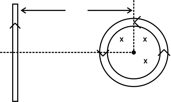
Example 3: A square loop of side ‘a’ and a straight, infinite conductor are placed in the same plane with two sides of the square parallel to the conductor. The inductance and resistance are equal to L and R respectively. The frame is turned through 1800 about the axis OO’. Find the electric charge that flows in the square loop.
Integrating above equation w.r.t time we get
| ∫ | Ri dt | − | ∫ | L | = | φ − φ i | ||||||||||
|---|---|---|---|---|---|---|---|---|---|---|---|---|---|---|---|---|
| ⇒ | Rq | = | ∫ | − |
|
− | L [i] i f | |||||||||
| (i | initial = 0, i final |
= | 0 | |||||||||||||
| ⇒ | / R | |||||||||||||||
|
gt 1 | = |
|
|||||||||||||
|---|---|---|---|---|---|---|---|---|---|---|---|---|---|---|---|---|
| E | = − | d | φ | |||||||||||||
| dt | ||||||||||||||||
| and induced current I | = − | BvW |
|
|||||||||||||
| R | ||||||||||||||||
|
= − | B vW 2 | ||||||||||||||
| R | ||||||||||||||||
| So, m | dv | = | mg | − | B vW 2 | |||||||||||
| dt | R | |||||||||||||||
| At t | = | t , v 1 | = | v | 1 | = | gt 1 |
|
|
||||||||||||||
|---|---|---|---|---|---|---|---|---|---|---|---|---|---|---|---|---|---|---|---|---|---|---|---|
| A | = | t 1 | + | 2 | log e | − | 1 |
2 |
|
||||||||||||||
| B W 2 | R | y | A | ||||||||||||||||||||
| x | |||||||||||||||||||||||
| − | B W 2 | 2 | t t1 | ) | = | log e |
R |
||||||||||||||||
| mg | |||||||||||||||||||||||
| e | mR |
|
|||||||||||||||||||||
| O |
|
||||||||||||||||||||||
y
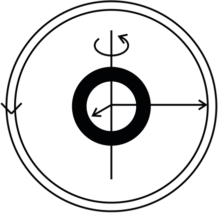
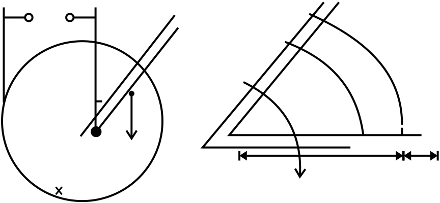
(a) As the terminals of the switch S are connected between the points O and C, so the e.m.f. across the switch is same as across the ends of the rod. Now to calculate the e.m.f. across the rod, consider an element of the rod of length dr at a distance r from O, then
current flows from lower to higher potential)
(b)(i) Treating the ring and rod rotating in the field as a source of e.m.f. E given by equation (i), the equivalent circuit (when the switch S is closed) is as shown in Figure.
| L | L | C |
|---|
(i) Obtain an expression for the current as a function of time
(ii) In the steady state, obtained the time dependence of the torque required to maintain the constant angular speed, given that the rod OA was along the positive x-axis at t=0.
| I | = | B l 2 | 1 | − | e | − | ( R/L t ) | … (ii) | |
|---|---|---|---|---|---|---|---|---|---|
| 2R | |
Physics | 22.35
| The instantaneous fluxφ is given by | φ = | B | × | d | × | |||||||
| E | = − | d φ | = −Bd | | dx |
|
||||||
| dt | | dt | ||||||||||
|
||||||||||||
| τ = | | M | g cos | θ+ | BI | rdr | = | Mgl | cos | θ + | BI |
|
= ( R
Bd |
⇒ | dx | = | i R ( | + λ 2 x |
|
|||||||||||||||||||
| | l | 2 | dt | + λ 2 x | ||||||||||||||||||||||||||||||||||
| ) i.e., velocity | ||||||||||||||||||||||||||||||||||||||
|
||||||||||||||||||||||||||||||||||||||
| So, | τ = | Mgl | cos t ω + | B | 2 | ω l 4 | … (iv) | The instantaneous acceleration |
|
|||||||||||||||||||||||||||||
| 2 | ||||||||||||||||||||||||||||||||||||||
| a | = |
|
) |
| = | 2i 2 | λ | ( R | + λ 2 x | |||||||||||||||||||||||||||||
|
||||||||||||||||||||||||||||||||||||||
| = | ||||||||||||||||||||||||||||||||||||||
| |
|
|||||||||||||||||||||||||||||||||||||
| M | ||||||||||||||||||||||||||||||||||||||
| ∴ Instantaneous applied force | ||||||||||||||||||||||||||||||||||||||
| R |
|
B | d |
|
||||||||||||||||||||||||||||||||||
| N | R | + λ 2 x | ) | = | ||||||||||||||||||||||||||||||||||
|
||||||||||||||||||||||||||||||||||||||
|
= | FB d 2 2 | × | |||||||||||||||||||||||||||||||||||
| 2m λ | ||||||||||||||||||||||||||||||||||||||
( R + λ 2 x |
) | |||||||||||||||||||||||||||||||||||||
|
||||||||||||||||||||||||||||||||||||||
|
||||||||||||||||||||||||||||||||||||||
|
|---|
F= IaB
| d φ = | d | Bxd | ) | = | Bd | dx | = | ||
|---|---|---|---|---|---|---|---|---|---|
| dt | dt |
| mg | a | sin t ω = | 1 | |
|---|---|---|---|---|
| 2 | 2 |
| I | = | E | − |
|
= | mg sin t | ; | |||||
|---|---|---|---|---|---|---|---|---|---|---|---|---|
| aB | ω a 2 | |||||||||||
| ∴ | E | = | 1 | ( | 2 mgRsin | ω + | B 2 | |||||
| 2Ba | ||||||||||||
The force between the two wires due to current flow
| F | = | µ | 0 1 2 i i | .d | = | µ | 0 | × | 2I d 2 | |||||||
|---|---|---|---|---|---|---|---|---|---|---|---|---|---|---|---|---|
| 2 x | 4 | π | x |
|
||||||||||||
| = | 2d | |
|
| ||||||||||||
| x | ) | ρ | | |||||||||||||
| dP | = | 0 | ⇒ | Li 2 0 |
| − | 1 | e | − | t/ | τ | + | 2 | e | −2t/ | τ | | = | |||||||||||||||||||||
|---|---|---|---|---|---|---|---|---|---|---|---|---|---|---|---|---|---|---|---|---|---|---|---|---|---|---|---|---|---|---|---|---|---|---|---|---|---|---|---|
| dt | τ | |
τ | τ | | ||||||||||||||||||||||||||||||||||
| ⇒− | e | − | t/ | τ | = | 1 | |||||||||||||||||||||||||||||||||
| 2 | |||||||||||||||||||||||||||||||||||||||
|
|||||||||||||||||||||||||||||||||||||||
| ∴ | F resultant | = |
|
Putting in (i) | − | 1 | | = | = | E 2 | |||||||||||||||||||||||||||||
| P m ax | = | τ |
1 | ||||||||||||||||||||||||||||||||||||
|
− | µ | 2d | | Bdv | | |||||||||||||||||||||||||||||||||
| ( | L | / R | |||||||||||||||||||||||||||||||||||||
| = | 0 | | | 2 | 4 | | 4R | 2 | ( | ) | 4R | ||||||||||||||||||||||||||||
| ρ |
|
x | ) | ρ | | | ( | ) | |||||||||||||||||||||||||||||||
| = |
|
− | µ 0 | dv |
|
|||||||
|---|---|---|---|---|---|---|---|---|---|---|---|---|
| ρ | | 4 | π | ( d | + | x | ) | ρ | ||||
| µ 0dv | = | 1 | or x | = | µ | 0v | ||||
|---|---|---|---|---|---|---|---|---|---|---|
| 4 | π | ) | ρ | 4 | πρ |
|
|
σ = | q | = | CV (1 A | − | e | − | t/ | τ | ||||||||||||||||||||||||||||||||||||||||||||||||||||||||||||
|---|---|---|---|---|---|---|---|---|---|---|---|---|---|---|---|---|---|---|---|---|---|---|---|---|---|---|---|---|---|---|---|---|---|---|---|---|---|---|---|---|---|---|---|---|---|---|---|---|---|---|---|---|---|---|---|---|---|---|---|---|---|---|---|---|---|---|---|---|---|---|
| A | ||||||||||||||||||||||||||||||||||||||||||||||||||||||||||||||||||||||
| I | E | = | σ | = | CV | (1 | − | e | − | t/ | τ |
|
||||||||||||||||||||||||||||||||||||||||||||||||||||||||||
| R | + |
|
ε | 0 | ε | 0 | A | |||||||||||||||||||||||||||||||||||||||||||||||||||||||||||||||
| - | φ = E | EA | = | CV | (1 | − | e | − | t/ | τ | ||||||||||||||||||||||||||||||||||||||||||||||||||||||||||||
| L | ||||||||||||||||||||||||||||||||||||||||||||||||||||||||||||||||||||||
| ε | 0 | |||||||||||||||||||||||||||||||||||||||||||||||||||||||||||||||||||||
| i d | = ε | 0 | d | |||||||||||||||||||||||||||||||||||||||||||||||||||||||||||||||||||
|
|
|||||||||||||||||||||||||||||||||||||||||||||||||||||||||||||||||||||
| Or, | i d | = ε | 0 | d | CV | (1 | − | e | − | t/ | τ | ) | | = | CV | e | − | t/ | ||||||||||||||||||||||||||||||||||||||||||||||||||||
| U | = | Li 2 | = | 1 | ( 1 | − | e | − | τ |
|
||||||||||||||||||||||||||||||||||||||||||||||||||||||||||||
| 1 | t/ | dt | ε | 0 | |
τ | ||||||||||||||||||||||||||||||||||||||||||||||||||||||||||||||||
| 2 | 2 | |||||||||||||||||||||||||||||||||||||||||||||||||||||||||||||||||||||
|
τ = | CR where R | ′ | = | ||||||||||||||||||||||||||||||||||||||||||||||||||||||||||||||||||
| P | = | dU | = | ( 1 | − | e | − | t/ | τ | )( | −e | − | t/ | τ | ) | | 1 |
|
|
i d | = | V | e | − | ||||||||||||||||||||||||||||||||||||||||||||||
| − | τ | ) | | − | 2R | |||||||||||||||||||||||||||||||||||||||||||||||||||||||||||||||||
| dt | | τ | ||||||||||||||||||||||||||||||||||||||||||||||||||||||||||||||||||||
| = | ( | − | t/ | τ | − | e | −2t/ | τ |
|
C | = | ε |
|
|||||||||||||||||||||||||||||||||||||||||||||||||||||||||
| e | ||||||||||||||||||||||||||||||||||||||||||||||||||||||||||||||||||||||
| τ | ||||||||||||||||||||||||||||||||||||||||||||||||||||||||||||||||||||||
| i d | = | V | e | 2 | ||||||||||||||||||||||||||||||||||||||||||||||||||||||||||||||||||
| ε 0 | ||||||||||||||||||||||||||||||||||||||||||||||||||||||||||||||||||||||
| 2R | ||||||||||||||||||||||||||||||||||||||||||||||||||||||||||||||||||||||
22.38 | Electromagnetic Induction and Electromagnetic Waves
Exercise 1
| 4 | × | 10−4 | T. | |
Q.3 The self-inductance of an inductance coil having 100 turns is 20 mH. Calculate the magnetic flux through the cross-section of the coil corresponding to a current of 4 mA. Also find the total flux.
Q.4 A rectangular loop of wire is being withdrawn out of the magnetic field with velocity v. The magnetic field is perpendicular to the plane of paper. What will be the direction of induced current, in the loop?
Q.9 A square copper coil of each side 8 cm consists of 100 turns. The coil is initially in vertically plane, such that the plane of coil is normal to the uniform magnetic field of induction 0.4 weber m-2. The coil is turned through 1800 about a horizontal axis in 0.2s. Find the induced e.m.f.
Q.10 A 5 H inductor carries a steady current of 2 A. How can a 50 V self-induced e.m.f. be made to appear in the inductor?
Q.15 What is induced e.m.f.? Write faraday’s law of electromagnetic induction. Express it mathematically.
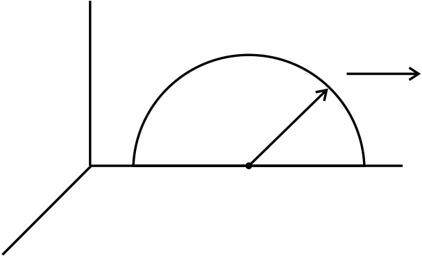
A conducting rod of length ‘l’, with one end pivoted, is rotated with a uniform angular speed' ' ω in a vertical plane, normal to a uniform magnetic field ‘B’. Deduce an expression for the e.m.f. induced in this rod.
|
� | P |  R R |
|
|---|---|---|---|---|
 Q
Q
 P
P
S
Deduce an expression for
Q 24 The identical loops, one of copper and the other of aluminum, are rotated with the same angular speed in the same magnetic field. Compare (i) the induced e.m.f. and (ii) the current produced in the two coils. Justify your answer.
Q.25 Two bar magnets are quickly moved towards a metallic loop connected across a capacitor ‘C’ as shown in the Figure. Predict the polarity of the capacitor.
|
Q |
|
C | 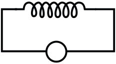 A A |
||
|---|---|---|---|---|---|---|
| Exercise 2 | ||||||
|
||||||
 A
A
(ii) A jet plane is travelling towards west at a speed of 1800 km/h. what is the voltage difference developed between the ends of the wing having a span of 25m, if the earth’s magnetic field at the location has a magnitude of 5×10⁻⁴ T and the dip angle is 300?
|
|
|
|---|---|---|
|
Q.2 A square wire loop of 10.0 cm side lies at right angle to a uniform magnetic field of 20T. A 10V light bulb is in a series with the loop as shown in the Figure. The magnetic field is decreasing steadily to zero over a time interval t∆ . The bulb will shine full brightness if ∆ is equal to
i i
(A)
t (B)
t
(C) 0 V (D) none of these
Q.5 Two identical coaxial circular loops carry a current I each circulating in the same direction. If the loops approach each other
Physics | 22.41
| I | r | � |
|
|---|---|---|---|
| l | |||

in the xy plane with velocity v i x+ v j y . The potential
difference between A and C is proportional to
| B | L 2 | + | l 2 |
|
(B) |
|
||||
|---|---|---|---|---|---|---|---|---|---|---|
| 1B 2ω | ( | L 2 | + | l 2 | (D) | |||||
| P | 5m |
|
x |
|
|---|---|---|---|---|
Q.12 The magnetic field in a region is given by
Q.15 A rectangular coil of single turn, having area A, rotates in a uniform magnetic field B with an angular velocity w about an axis perpendicular to the field. If initially the plane of coil is perpendicular to the field, then the average induced e.m.f. when it has rotated through 900 is
| C | A | L |
|---|
| (A) | B l 2 | (B) | B l 2 | (C) | 3B l 2 | (D) | 3B l 2 |
|---|---|---|---|---|---|---|---|
| 4 | 2 | 4 | 8 |
(C) Is repelled by the loop-A
(D) Rotates about its CM, with CM fixedQ.21 A circular loop of radius R, carrying current I, lies in x-y plane with its center at origin. The total magnetic flux through x-y plane is
(A) Directly proportional to I
(B) Directly proportional to R
(C)Directly proportional to R2
(D) Zero
| (a) | (b) |
|
||
|---|---|---|---|---|
|
||||
| (A) | µ | 0R | (B) | µ π 0R | (C) | µ | 0 | (D) 0 |
|---|---|---|---|---|---|---|---|---|
| 2 | 2 | |||||||
(C) Maximum in situation (c)
(D) The same in all situations
|
(B) BLv/R anticlockwise |
|
r | P | ||
|---|---|---|---|---|---|---|
|
|
|||||
N
| (B) | B | νπ R / 2 2 |
|---|
(D)2RBν and Q is at higher potential
Q.3 A metal rod moves at a constant velocity in a direction perpendicular to its length. A constant magnetic field exist in space in a direction perpendicular to the rod as well as its velocity. Select the correct statement (s) from the following. (1998)
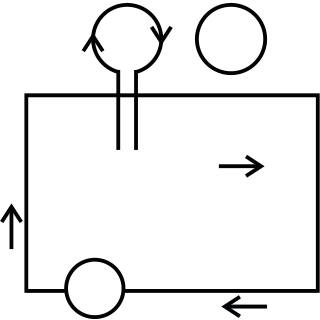
Q.7 A coil of wire having finite inductance and resistance has a conducting ring placed co-axially within it. The coil is connected to a battery at time t=0, so that a time dependent current I1 (t) starts flowing through the coil. I2 (t) is the current induced in the ring and B (t) is the magnetic field at the axis of the coil due to I1 (t) then as a function of time (t>0), the product I2 (t) B(t) (2000)
(A) Increases with time
|
||
|---|---|---|
| (2013) | ||
R S1 |
||
(B) Both clockwise
(C) Both anticlockwise
Q.11 An electromagnetic wave in vacuum has the
electric and magnetic fields E and B, which are
(C) X||B and k || E ×B (D) X||E and k || B ×E
Q.12 A coil is suspended in a uniform magnetic field, with the plane of the coil parallel to the magnetic lines of force. When a current is passed through the coil it starts oscillating; it is very difficult to stop. But if an aluminium plate is placed near to the coil, it stops. This is due to : (2012)
(B) At t=2τ, q=CV(1-e-2)
| (C) At t= | τ | , q=CV (1-e-1)−1 |
|
|---|---|---|---|
| 2 |
| (a) |
|
|
|
| (b) | Radio waves | (ii) | |
| (c) | (iii) | ||
| (d) |
|
(iv) | Absorbed by the ozone layer of the atmosphere |

|
(A) | 2 Q Max |
Q0 |
|
C | (B) | 2 Q Max |
L1 | L2 | t | |
|---|---|---|---|---|---|---|---|---|---|---|---|
| (2014) | |||||||||||
|
|||||||||||
|
|||||||||||
| t | |||||||||||
| ( ) | 2 Q Max |
(D) | 2 Q Max |
L2 | t | ||||||
|
|||||||||||
|
|||||||||||
| t | |||||||||||
Q.21 Two long current carrying
thin wires, both with current I, are L held by insulating threads of �
length L and are in equilibrium as
shown in the figure, with threads I
I making an angle ' 'θ with the
vertical. If wires have mass λ per unit length then the value of I is: (g=gravitational acceleration) (2015)
| (A) -1 (B) 1 | − | e | B | e | L | (A) | 2sin | πλ gL |
(B) | π gL | tan | θ | |||||||||
|---|---|---|---|---|---|---|---|---|---|---|---|---|---|---|---|---|---|---|---|---|---|
| µ |
|
||||||||||||||||||||
| (C) | (D) 1 | (C) |
|
(D) | sin | θ | µ | πλ | gL | ||||||||||||
| cos | |||||||||||||||||||||
| e | 1 | − | e | 0 | |||||||||||||||||
| (C) 0.67 mA | (A) | π 2 | (B) | π 2 | (C) | (D) | π 2 | ||
|---|---|---|---|---|---|---|---|---|---|
| 16 | 8 |
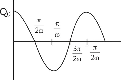
Q.20 An LCR circuit is equivalent to a damped pendulum. In an LCR circuit the capacitor is charged to Q0 and then connected to the L and R as shown. If a student plots graphs of the square of maximum charge (Q Max 2 )on the capacitor with time (t) for two different values L1 and L2 (L1 > L2) of L then which of the following represents this graph correctly? (Plots are schematic and not drawn to scale) (2015)
Q.23 Arrange the following electromagnetic radiations
(C) (2), (1), (4), (3) (D) (4), (2), (1), (3)
| JEE Advanced/Boards |
|---|
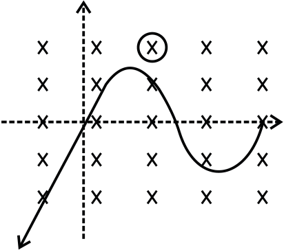
Q.2 A wire forming one cycle sine curve is moved in x-y
plane with velocity V = V i x ˆ + V j. y ˆ There exist a magnetic
field is B = −B k 0ˆ . Find the motional e.m.f. develop
Q.3 A conducting circular loop is placed in a uniform magnetic field of 0.02 T, with its plane perpendicular to the field. If the radius of the loop starts shrinking at a constant rate of 1.0 mm/s, then find the e.m.f. induced in the loop, at the instant when the radius is 4 cm.
C
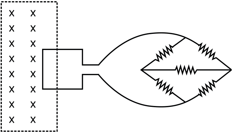
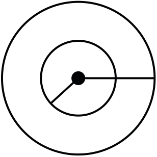
Q.5 Two concentric and coplanar circular coils have radii a and b(>>a) as shown in Figure. Resistance of the inner coil is R. Current in the outer coil is increased from 0 to i, then find the total charge circulating the inner coil.
b
B�
R
B
5.2m/s
| 90 o |
|---|
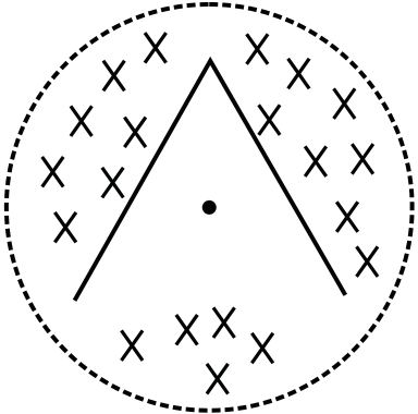
(ii) The e.m.f. around the triangle at that time.
(iii) In what manner does the e.m.f. around the triangle vary with time?
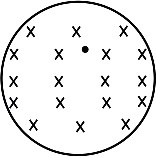
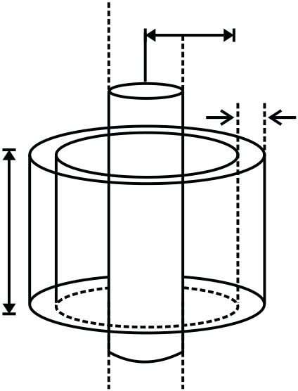
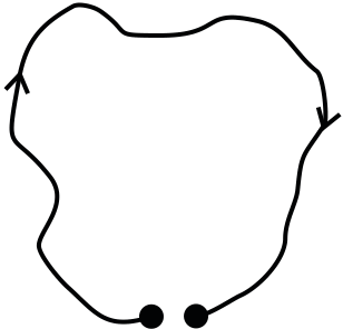
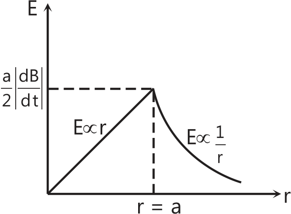
Q.10 There exists a uniform cylindrically symmetric magnetic field directed along the axis of a cylinder but varying with time as B=kt. If an electron is released from rest in this filed at a distance ‘r’ from the axis of cylinder, its acceleration, just after it is released would be (e and m are the electronic charge and mass respectively)
Q.11 A uniform but time varying magnetic field B=Kt–C; (0 ≤ t ≤ C/K), where K and C are constants and t is time, is applied perpendicular to the plane of the circular loop of radius ’a’ and resistance R. Find the total charge that will pass around the loop.
x
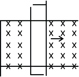
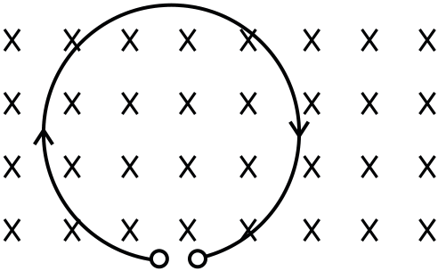
(i) If a magnetic field B points in the positive x direction, what is the magnitude of the e.m.f. developed in the wire, when B increases at the rate of 3 mT/s?
22.48 | Electromagnetic Induction and Electromagnetic Waves
|
||||
|---|---|---|---|---|
| A | E |
|
||
| � | ||||
| v | B | D | F |
|

a
(i) The terminal velocity achieved by the rod.
(ii) The acceleration of the mass at the instant when the velocity of the rod is half the terminal velocity.
y

| (C) | µ | 0er | 2 | |||
|---|---|---|---|---|---|---|
|
4 R | |||||
(ii) The total Lorentz force acting on the loop and indicated its direction,
a
(a) Calculate maximum current in the square loop.
Q.2 A closed planar wire loop of area A and arbitrary shape is placed in a uniform magnetic field of magnitude B, with its plane perpendicular to magnitude to magnetic field. The resistance of the wire loop is R. The loop is now turned upside down by 180o so that its plane again becomes perpendicular to the magnetic field. The total charge that must have flowed through the wire in the process is
R |
(B) | 2B | 2 2 |
vx | 4B |
|
|
|---|
|
|
|---|
|
(D) F= |
|---|
22.50 | Electromagnetic Induction and Electromagnetic Waves
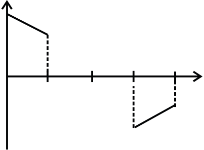
Q.7An equilateral triangle loop ADC of some finite B as shown in the Figure. At time t=0, side DC of loop is at edge of the magnetic field. Magnetic field is perpendicular to the paper inwards (or perpendicular to the plane of the coil). The induced current versus time graph will be as
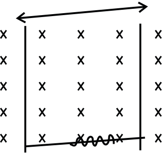
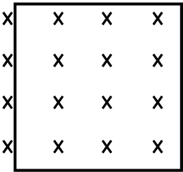
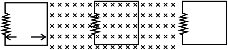
Q.11 A conducting wire is placed in a magnetic field which is directed into the paper. The magnetic field is increasing at a constant rate. The directions of induced currents in wire AB and CD are
| (A) | i |  t t |
D | V | C |
|
||
|---|---|---|---|---|---|---|---|---|
|
||||||||
| (B) | I1 | |||||||
( )
t (D)
t
Q.8 A ring of resistance 10 Ω, radius 10cm and 100 turns is rotated at a rate 100 rev/s about its diameter is perpendicular to a uniform magnetic field of induction 10mT. The amplitude of the current in the loop will be nearly (take: π 2 = 10 )
(C) BN/AL (D) B/ANL
Q.10 A small square loop of wire of side l is placed inside a large square loop of wire of side L (L>>l). The loop are co-planner & their centers coincide. The mutual inductance of the system is proportional to:
(D) When 1≠0 and I 2≠0 are in opposite directions then the coils tends to move apart.
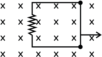
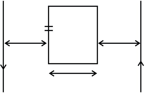
Q.13 A conducting rod PQ of length L= 1.0 m is moving with a uniform speed v=20 m/s in a uniform magnetic field B=4.0T directed into the paper. A capacitor of capacity C= 10 F µ is connected as shown in Figure. Then P
(B) q A = −800 Candq B = + 800 C
(C) q A = 0 = q B
Q.14 The e.m.f. induced in a coil of wire, which is rotating in a magnetic field, does not depend on
(A) The angular speed of rotation
(B) The area of the coil
(C) The number of turns on the coil
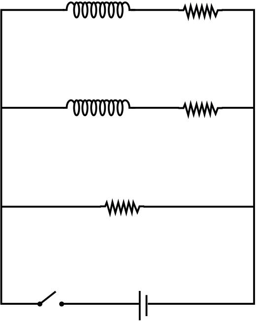
(D) The resistance of the coilQ.15 Current growth in two L-R circuit (b) and (c) as shown in Figure (a). Let L1,L2, R2 and R2 be the corresponding value in two circuits, then
| (b) | (b) | L1 | ( ) | L1 | R1 |
|---|
(B) There will be attraction between A and B if i is increased
(C) There will be neither attraction nor repulsion when i is changed
(C) The south pole faces the ring and the magnet moves away from it.
(D) The north pole faces the ring and the magnet moves away from it.
| P | R | |||||
|---|---|---|---|---|---|---|
| Q |
|
|||||
|
||||||
|
||||||
|
B | F | ||||
| C | B | |||||
|
||||||
| (B) At point Q is anticlockwise | � |
|
||||
| A | B |
|
|---|---|---|
|
||
22.52 | Electromagnetic Induction and Electromagnetic Waves
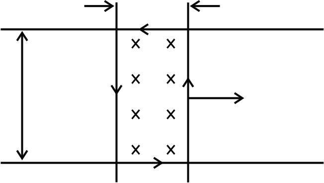
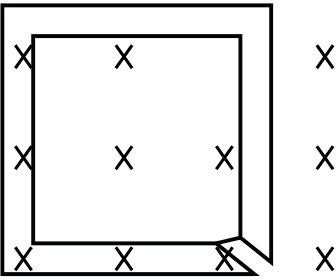
Q.24 The Figure shows certain wire segments joined together to form a coplanar loop. The loop is placed in a perpendicular magnetic field in the direction going into the plane of the figure. The magnitude of the field increases with time.I1 and I2 are the currents in the segments ab and cd. Then,
 |
c |
|
b |
|---|
| (B) 1 | < | I |
|
|---|
Physics | 22.53
Comprehension Type
( ) Case I : Φ = π ( L 2 +2 ) B
CaseII : Φ = π ( L 2−2 ) B
| (A) | V P | − | V 0 | > | 0 and V R | − | V 0 | < |
|
|
|||||||||
|---|---|---|---|---|---|---|---|---|---|---|---|---|---|---|---|---|---|---|---|
| (B) | V P | = | V R | > | |||||||||||||||
| (C) | V 0 | > | V P | = | |||||||||||||||
| (D) | V Q | − | V P | = | V P | − | V 0 |
|
|||||||||||
Q.28 Choose correct statement (s) related to the magnitude of potential differences
| (B) 1 | > |
|
|---|
| Q | → | P | → | O and Q | → | R | → |
|---|
Q.34 Match the Following Columns
| (A) |
|
||
| (B) |
|
(Q) | |
| (C) | (R) | Induced electric filed | |
| (D) |
|


(B) Anticlockwise of the + ve z-axis
(C) Zero
| (A) 1 | > | I |
|
|---|---|---|---|
| (B) 1 | > | I |
(A) IBL (B) IBL π (C) IBL 2π (D) IBL


Physics | 22.55
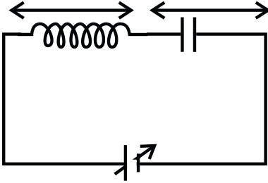
(A) At t=0, energy stored in the circuit is purely in the
form of magnetic energy
| R | C | S1 | ||
|---|---|---|---|---|
| S2 |
|
|||
| the circuit may be V |
|
|||
|
||||||||||||||||
|---|---|---|---|---|---|---|---|---|---|---|---|---|---|---|---|---|
| (1994) | ||||||||||||||||
| (A) | i 1 | = | 1 |
|
= | 4 | (C) | W 1 | = |
|
(D) | V 1 V= 2 |
||||
| i 2 | 4 | i 2 | W 2 | (C) 40 | ||||||||||||
Q.9 A series R-C circuit is connected to AC voltage source. Consider two cases; (A) when C is without a dielectric medium and (B) when C is filled C is filled with dielectric of constant 4. The current IR through the resistor and VC across the capacitor are compared in the two cases. Which of the following is/are true? (2011)
Q.13 In the method using the transformers, assume that the ratio of the number of turns in the primary to that in the secondary in the step-up transformer is 1 : 10. If the power to the consumers has to be supplied at 200 V, the ratio of the number of turns in the primary to that in the secondary in the step-down transformer is (2013)
| at z | = |  3R 3R |
along the axis of the circular wire loop, as |
|---|---|---|---|
|
|||
(D) There is a repulsive force between the wire and the loop
| 3L | 4L | x | |||||||||||||||||||
|---|---|---|---|---|---|---|---|---|---|---|---|---|---|---|---|---|---|---|---|---|---|
| I(x) | F(x) | ||||||||||||||||||||
| (A) |
|
(B) | 0 | L | 2L | ||||||||||||||||
| 0 | L | 2L | 3L | ||||||||||||||||||
|
3L | 4L | x | ||||||||||||||||||
|
|||||||||||||||||||||
| v(x) | |||||||||||||||||||||
| ( ) | 0 | L | 2L | 3L | 4L | (D) | |||||||||||||||
|
|||||||||||||||||||||
| 0 | L | 2L | |||||||||||||||||||
|
|||||||||||||||||||||
| (B) | 0 | L | 2L | 3L | 4L |
|
|||||||||||||||
|
|||||||||||||||||||||
| 0 | L | 2L | 3L | ||||||||||||||||||
JEE Main/Boards
JEE Advanced/Boards
| Q.1 C | Q.2 A | Q.3 A | Q.4 C | Q.5 A | Q.6 D |
|---|---|---|---|---|---|
| Q.7 A | Q.8 A | Q.9 B | Q.10 C | Q.11 A | Q.12 A |
| Q.13 C | Q.14 A | Q.15 D | Q.16 D | Q.17 B | Q18 B |
| Q.19 D | Q.20 C | Q.21 D | Q.22 A |
| Q.2 | λ |
|
||||
|---|---|---|---|---|---|---|
| Q.4 2N | ||||||
| Q.5 | µ | 0ia 2 | π | Q.6 |
|
|
| 2Rb | ||||||
| Q.17 | µ | 0 | ih i N m | � | s | |||||||||||||||||||||||||||||||||||
|---|---|---|---|---|---|---|---|---|---|---|---|---|---|---|---|---|---|---|---|---|---|---|---|---|---|---|---|---|---|---|---|---|---|---|---|---|---|---|---|---|
| F | ||||||||||||||||||||||||||||||||||||||||
| s | ||||||||||||||||||||||||||||||||||||||||
| Q.18 | 2 | − |
|
|||||||||||||||||||||||||||||||||||||
| 2 | = | 1 | e | −Rt/L | | |||||||||||||||||||||||||||||||||||
| Q.19 EA | = | 7 | Al; i BE | = | 3 | A; i FE | Q.20 (i) E= | 1B r 2 | 2 | (ii) | I | = | B r | 2 | 1 | − | ||||||||||||||||||||||||
| 22 | 11 | 22 | 2R | |||||||||||||||||||||||||||||||||||||
| Q.21 (i) | V terminal | = | mgR | |||||||||||||||||||||||||||||||||||||
| B L 2 2 | Q.23 | I | = | ( | µ | 0 | ni cos t 0 | ) | π a 2 | ( | Ld | |||||||||||||||||||||||||||||
| Q.22 (a) Imax= | µ π 0 aCI 0 | ω 2 |
|
|||||||||||||||||||||||||||||||||||||
| ρ π 2 R | ||||||||||||||||||||||||||||||||||||||||
(b) Qo
Single Correct Choice Type
| Q.1 B | Q.2 C | Q.3 D | Q.4 A | Q.5 B | Q.6 A |
|---|---|---|---|---|---|
| Q.7 B | Q.8 B | Q.9 A | Q.10 B |
Multiple Correct Choice Type
| Q.27 B, D | Q.28 A, C | Q.29 D | Q.30 C | Q.31 C | Q.32 B |
|---|
Q.33 B
Match the Column Type
|
||
|---|---|---|
| JEE Main/Boards Exercise 1 | N∈=– | |
| µ0nNA=M | ||
(∆A=2A as it turned through 180o)
| = | 4 | × | 10 | –4 | × | 10 3 | × | 500 10 | –4 | × | 2 |
|
|---|---|---|---|---|---|---|---|---|---|---|---|---|
| 1 |
M=4π×10–7 × 50 × 102 × 200 × 4 × 10–4 =5.03 × 10⁻⁴ H
|
|
|---|---|
2
|
L. | 4 | |||||
|---|---|---|---|---|---|---|---|
|
10 10 | –6 | |||||
| µ | |||||||
|
|||||||
|
|||||||
| df= |
|
||||||
|
|||||||
| ε =d φ = | 2.77 10 | –7 |
|
|
|---|---|---|---|---|
| dt |
|
|||
| ε = |
|
|---|
| L | 2 | = | µ | 2 |
|---|---|---|---|---|
| L 1 | µ 1 | |||
| 2 | ||||
|---|---|---|---|---|
| π=N | ∴ L= | µ | 0N r | |
| | | |||
Sol 14: ε =–L
dtdiSolenoid tries to go back to initial state i.e. If an action produce a change ∆ε1, solenoid tries to produce a change ∆ε2 such that ∆ε2 is in Opposite direction of ∆ε1.
 |
|
|
|---|---|---|
|
||
ε = 2πr2w B
(ii) Current in copper is more, as its resistance is less.
Physics | 22.63
| Sol 19 : (D) E= | ||
|---|---|---|
|
B.dA=0 Q E=0 ⇒ L=0
Note: Simply we can say. The magnetic field vectors will be along the plant.∴ Magnetic flux linked with smaller loop
f=B.S
Therefore, the mutual inductance
| M= i φ =K |
|
or M ∝ |
|---|
∴ in others it is minimum, maximum in (a)
Previous Years’ Questions
|
i=i0( | 1 – e | –t/tL |
|
… (i) |
|---|---|---|---|---|---|
eMNQ=eMQ=Bvl=Bv(2R) [=MQ=2R]
Therefore, potential difference developed across the ring is 2RBv with Q at higher potential.
and i=1A(given), t=?
 |
|
|||
|---|---|---|---|---|
 |
∴ E= | a 2 | ||
 |
||||
 |
2r | |||
|
|
|||||
|---|---|---|---|---|---|---|
 |
|
|||||
|
||||||
|
||||||
| r |
|
|||||
| B(t)=K3(1– | e | –k t 2 | ∴ | P P=4 1 |
|||
|---|---|---|---|---|---|---|---|
| I2(t)=K4 | e | –k t 2 | |||||
magnetic field,
∴ X || B
|
|||||||||||||
|---|---|---|---|---|---|---|---|---|---|---|---|---|---|
| q | = | CV(1 | − | e | − | t/ | τ | ||||||
| At t | = | ||||||||||||
| q | = | CV(1 | − | e | −2 | ) | |||||||
|
2 | 1 |
|
||||||||||
| R | |||||||||||||
X-rays → To detect fracture of bones
Ultraviolet rays → Absorbed by the ozone layer of the atmosphere;
Sol 24 : (C) For electromagnet and transformer, the coercivity should be low to reduce energy loss.
JEE Advanced/Boards
| I | 0 | = | Exercise 1 | |
|---|---|---|---|---|
Sol 20 : (D)
| As | L | > | L | , therefore | 1 | L i 2 | > | 1 | L 2 | > | 1 | L i 2 |
|
|
|---|---|---|---|---|---|---|---|---|---|---|---|---|---|---|
| 1 | 2 | 2 | 1 | 2 | 2 | 2 |
Sol 2 : E =(V×B).
V= v i + xˆ v i yˆ
Physics | 22.67
=– B2πr .dr dt =(0.02) . 2π (4 × 10⁻²) . (1 × 10⁻³) =5 µV
| ⇒ 1= | 4 |
|
||||
|---|---|---|---|---|---|---|
| 2 | + | 1 | ||||
| 1 | + | 1 | ||||
| 6 | 3 |
⇒ F=ib = 1 × 1 × 2 = 2 N
| ∈=d dtBA = | d | π a . 2 µ | 0 | i | |||||||||
|---|---|---|---|---|---|---|---|---|---|---|---|---|---|
| dt | 2b | ||||||||||||
| ∈= | π a 2 | µ | 0 | ||||||||||
| 2b | |||||||||||||
| ∈ =iR = | dQ R dt |
||||||||||||
| ⇒ | dQ R |
π a 2 | µ | 0 | di | ||||||||
| 2b | dt | ||||||||||||
Let AB be diameter rod, CD be external resistor CD is fixed
| E= | = | BR d 2 |
|
||||||||||
|---|---|---|---|---|---|---|---|---|---|---|---|---|---|
| 2 |
|
||||||||||||
| E= | BR w 2 | = | 500 | × | (0.1) 2 | × | 20 | ||||||
| 2 | 2 | ||||||||||||
| RAC= | R | AB | |||||||||||
| 2 | |||||||||||||
| A dB | = | 3 | a . 2 | dB = | ||
|---|---|---|---|---|---|---|
| dt | 4 |
|
E=3V
| ⇒∆Q= | = | π a 2 | µ | 0 |
|
|||||||||
|---|---|---|---|---|---|---|---|---|---|---|---|---|---|---|
| 2bR |
|
|||||||||||||
| B | 2 2 | v | ||||||||||||
|
||||||||||||||
|
||||||||||||||
 |
||||||||||||||
| R | ||||||||||||||
|
||||||||||||||
| ⇒ mg – | B 2 2 |
v | =0 ⇒ v= | |||||||||||
| AdB | ||||||||||||||
| R | ||||||||||||||
22.68 | Electromagnetic Induction and Electromagnetic Waves
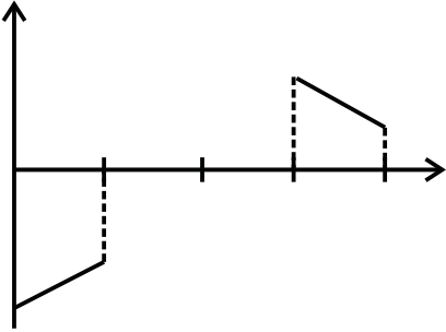
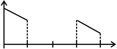
e=– Bv 0< x < w=0 w < x < 3w=Bvw < x < 4w Sol 17 : B.ds∫ =µ0ienc
B.2πr=µ0im in cos wt
| Sol 16 : f=Bvt | | 0 | < | t | < | w |
|
B= | µ | 0Nim cos | |||||||||||||||||||||||||||||||||
|---|---|---|---|---|---|---|---|---|---|---|---|---|---|---|---|---|---|---|---|---|---|---|---|---|---|---|---|---|---|---|---|---|---|---|---|---|---|---|---|---|---|---|---|
| v | |||||||||||||||||||||||||||||||||||||||||||
| | 2 r | ||||||||||||||||||||||||||||||||||||||||||
| =Bw | w | < | t | < | 3w |
|
df= | µ 0 | 0N imcos t |
|
|||||||||||||||||||||||||||||||||
| v | v | ||||||||||||||||||||||||||||||||||||||||||
| 2 | |||||||||||||||||||||||||||||||||||||||||||
| 3w | < | t | < | 4w |
|
⇒ f= | µ | 0N imcos t |
|
||||||||||||||||||||||||||||||||||
| v | v | ||||||||||||||||||||||||||||||||||||||||||
| 2 | |||||||||||||||||||||||||||||||||||||||||||
dt |
w µ | 0 N imhsin t |
|
||||||||||||||||||||||||||||||||||||||||
| 2 | π | ||||||||||||||||||||||||||||||||||||||||||
| ⇒ e=– Blv | 0 | < | t | < | w | ||||||||||||||||||||||||||||||||||||||
| Amplitude= | µ | 0 N hi m | |||||||||||||||||||||||||||||||||||||||||
| v | |||||||||||||||||||||||||||||||||||||||||||
| 2 | |||||||||||||||||||||||||||||||||||||||||||
| =0 |
|
w | < | t | < | 3w |
|
||||||||||||||||||||||||||||||||||||
| v | v | Sol 18 : | |||||||||||||||||||||||||||||||||||||||||
| =Bv | 3 ω | < | t | < | 3 ω | ||||||||||||||||||||||||||||||||||||||
| v | v | ||||||||||||||||||||||||||||||||||||||||||
| F=iB= |
|
||||||||||||||||||||||||||||||||||||||||||
| ⇒ E= | – | | 2 B V 2 |
|
0 | < | t | < | w | ||||||||||||||||||||||||||||||||||
| e= | |||||||||||||||||||||||||||||||||||||||||||
| v | |||||||||||||||||||||||||||||||||||||||||||
| = 0 | w | < | t | < | 3w |
|
⇒ e1= |
|
|||||||||||||||||||||||||||||||||||
| v | v | ||||||||||||||||||||||||||||||||||||||||||
| = | – | 2 2 B v | 3w | < | t | < | 4w | ⇒ e2= | A | 2 | dB | ||||||||||||||||||||||||||||||||
| – | | ||||||||||||||||||||||||||||||||||||||||||
| v | v | ||||||||||||||||||||||||||||||||||||||||||
|
|||||||||||||||||||||||||||||||||||||||||||
|
|||||||||||||||||||||||||||||||||||||||||||
| A1 – A2= | 2 |
R –2 | |||||||||||||||||||||||||||||||||||||||||
| ∴e= |
|
R –2 |
|
||||||||||||||||||||||||||||||||||||||||
| ⇒ e2= | A |
1 | |||||||||||||||||||||||||||||||||||||||||
| i11= | 3 | + | e 1 | 1 | ||||||
|---|---|---|---|---|---|---|---|---|---|---|
| 1 | ||||||||||
| 1 | + | |||||||||
| 2 | ||||||||||
| i13= | 2 | 2 | 1 |
|
||||||
| + | ||||||||||
|
||||||||||
| i22= | 2 | e 2 | 1 | =2 A 11 |
||||||
| 1 | ||||||||||
| 1 | + | |||||||||
| 3 | ||||||||||
| i23= | 3 | 3 | 1 | |||||||
| + | ||||||||||
| iAE=3 11 | + | 1 | =7 A 22 |
|||||||
| 22 | ||||||||||
| iEf=2 11 | – | |||||||||
| iEB=1 11 | + | 2 | =3 A 11 |
|||||||
| 11 | ||||||||||
Sol 20 : (i)d∈=Bvdr
dTm=rdE
(Tm=torque due to magnetic field)
dFm=Bid
Bidr
(tm=magnetic force)
d.Tm=Birdr
fg=mg cos θ (fg=force of graving)
|
|||||||||
|---|---|---|---|---|---|---|---|---|---|
| ∴ T=mgrcos | θ + | ω | B r 2 4 | | 1 – e |
|
|||
| 2 |
|
| |||||||
| = | B L V 2 2 |
|---|---|
| R |
Physics | 22.71
| ⇒ v= | mgR | Integrating on both sides. | ||||||||||
|---|---|---|---|---|---|---|---|---|---|---|---|---|
|
||||||||||||
| (ii) Fm= | 2 2 | –mR | ln | |||||||||
| | V | | B a 2 2 | B a v 2 2 | ||||||||
| R | | 2 | |
|
0 | g – |
|
0 | ||||
| | | mR | ||||||||||
| ⇒ | g 1 – e |
–B a t 2 2 0 |
|||||||||
|---|---|---|---|---|---|---|---|---|---|---|---|
| (iii) (a) df=B.dy = | ⇒ v= | mgR | |
1 – e | –B a t 2 2 o |
||||||
| 2 1 |
|
B a 2 2 |
|||||||||
| Sol 22 : (a) B= | µ | 0i |
|---|---|---|
| 2 r | ||
Force due to it be f,
| = |
|
(v=dy dt= | dy dt= |
df,= | |||||||||||||||||||||||
|---|---|---|---|---|---|---|---|---|---|---|---|---|---|---|---|---|---|---|---|---|---|---|---|---|---|---|---|
| f1= |
|
||||||||||||||||||||||||||
i= R ε= d |
f1= | µ | 0Ia | ||||||||||||||||||||||||
| (y – y ) |
|
2 r |
|
||||||||||||||||||||||||
| Similarly f2= | |||||||||||||||||||||||||||
| = i a | | B y 0 | 2 | – | B y 0 | 1 | = | B av 0 | .a | | B | 0 | |||||||||||||||
| ∴f=f1 + f2=µ0Ialn 2 | |||||||||||||||||||||||||||
| | a | a | R | | a |
|
|
||||||||||||||||||||
| Fm= | f= | µ | |||||||||||||||||||||||||
| π | |||||||||||||||||||||||||||
| e=–d φ =– |
|
cos wt |
|---|---|---|
| ω 2 I aln2) 0 |


22.72 | Electromagnetic Induction and Electromagnetic Waves
 |
|
|
|---|---|---|
| Q0= |
|
|
Sol 5 : (B) Here power Supplied=Heat generated as no other element is using I,
⇒F . V=Q ⇒ F=Q
VSol 6 : (A) area of loop A=a2
∴DQ=2AB
R
Q
c=– BLv
Q=BlVC=4 × 1 × 20 × 10 × 10–6=800 µC
Phas greater potential than Q as
[V × B] is directed towards P
Sol 10 : (B) B ∝1
L
Sol 11 : (A) Induced current is along DC for loop DC. For loop AB it should be along AB but since area of CD loop is greater than AB loop, hence current is along BA.
| e= | CD | – A | AB |
|
||
|---|---|---|---|---|---|---|
|
||||||
| ∴A cos DC | ||||||
22.74 | Electromagnetic Induction and Electromagnetic Waves
Sol 21 : (B) fm would be along rats ∴f1=(L2 + 2)B
Sol 32 : (B) Clockwise overall current
Sol 25 : (B, D) Assume mA=mB A → P
Then iA>iB (hA>hB)
⇒ PA> PB
Now is mA<mB and PA> PB then surely hA>hB(C) Current in a ring produces magnetic field hence induced electric field
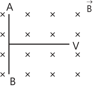
Sol 27 : (B, D) C → Q, S
| ⇒ e= | B r |
|
|||
|---|---|---|---|---|---|
| 2 | |||||
| VP–V0= |
|
||||
| VQ – V0= | Bw(2a) 2 | ||||
| 2 | |||||
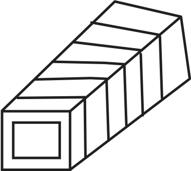
Sol 30 : (C) f= B.dA∫
Case I : A=L2 + 2µ=πr2I0 cos wt
µ charges with time,
⇒ magnetic moment charge Q, R, S
Physics | 22.75
∴R=L
2π
2T sin(dθ)=Fm
From small angles, sin(dθ)=dθIn circuit (p) : I can’t be non-zero in steady state.
In circuit (q)
| d Q 2 | =– w2Q | d Q 2 | |||
|---|---|---|---|---|---|
| dt | 2 | ∴ Q=– LC | |||
| dt | 2 | ||||
|
|
V | = | |||||||
|---|---|---|---|---|---|---|---|---|---|---|
| ∴ | L | 2 |
|
|||||||
| L 1 |
|
|
||||||||
| ∴ | W 2 W= 1 |
| L | 2 |
|
|
i 2 |
|
2 | | (4)2or | |||||||||||||||||||||
|---|---|---|---|---|---|---|---|---|---|---|---|---|---|---|---|---|---|---|---|---|---|---|---|---|---|---|---|---|---|---|---|---|
| | L 1 | |
i 1 | |||||||||||||||||||||||||||||
| V2=XCI= | | 1 | | I = | |
|
|
|
||||||||||||||||||||||||
| | 2 fC | | | 2 | π× | 50 | × ×3 10 | –3 | | Z= | R | 2 | + | X | 2 C |
= | R | 2 | 1 |
|
||||||||||||
|
ω C | |||||||||||||||||||||||||||||||
| VC= |
|
|
||||||||||||||||||||||||||||||
| q=q0(1 – | e | –t/ | ||||||||||||||||||||||||||||||

22.76 | Electromagnetic Induction and Electromagnetic Waves
At t=0, current will flow only in 12 Ω resistance
| ∴ | I min | = |
|
|---|---|---|---|
Sol 11 : (A, C)
| 2mH | ||||||||||||||||||||||||||||||||||||||||||||
|---|---|---|---|---|---|---|---|---|---|---|---|---|---|---|---|---|---|---|---|---|---|---|---|---|---|---|---|---|---|---|---|---|---|---|---|---|---|---|---|---|---|---|---|---|
5 V |
||||||||||||||||||||||||||||||||||||||||||||
| P | = | i R 2 | = | (150) (0.4 2 | × | 20) | = | 1.8 | × |
|
||||||||||||||||||||||||||||||||||
| Fraction (in %) | = | 1.8 10 5 | × | 100 | = | |||||||||||||||||||||||||||||||||||||||
| 6 10 5 | ||||||||||||||||||||||||||||||||||||||||||||
| = | ||||||||||||||||||||||||||||||||||||||||||||
|
i | = + |
|
|||||||||||||||||||||||||||||||||||||||||
| 45 o 45 o | ||||||||||||||||||||||||||||||||||||||||||||
| F | = | iLB | = | vB L 2 2 | ||||||||||||||||||||||||||||||||||||||||
| h=10 cm | 1 | |||||||||||||||||||||||||||||||||||||||||||
| R | ||||||||||||||||||||||||||||||||||||||||||||
| dr | ||||||||||||||||||||||||||||||||||||||||||||
| −mv |
= | B L 2 2 | ||||||||||||||||||||||||||||||||||||||||||
| φw |
|
µ | 0 | I | 2rdr | = | µ | 0 |
|
R | ||||||||||||||||||||||||||||||||||
| ∴ | v(x) | = | v | 0 | − | |||||||||||||||||||||||||||||||||||||||
| = | mR | |||||||||||||||||||||||||||||||||||||||||||
| 2 r | ||||||||||||||||||||||||||||||||||||||||||||
| i(x) | = | v BL 0 | − | B L 3 3 | ||||||||||||||||||||||||||||||||||||||||
| Mw | = | µ | 0 | h | ||||||||||||||||||||||||||||||||||||||||
| R | mR | 2 | ||||||||||||||||||||||||||||||||||||||||||
| F(x) | = |
|
− | B L 4 4 |
|
|||||||||||||||||||||||||||||||||||||||
| ∴ | ε | w | = | µ | 0 h di | = | µ | 0 | ||||||||||||||||||||||||||||||||||||
| R | mR | 2 | ||||||||||||||||||||||||||||||||||||||||||
| π | dt | |||||||||||||||||||||||||||||||||||||||||||