Chapter - 1 introduction and literature review
CHAPTER - 1 INTRODUCTION AND LITERATURE REVIEW
INTRODUCTION
A device which transfer fluids (liquids or gases), or sometimes slurries by mechanical actions is known as pump. According to their methods of moving fluids, pumps can be classified into three major groups: direct lift, displacement, gravity pumps. Pumps are operated by reciprocating mechanisms and consume energy to perform mechanical work by transferring the fluids. Manual operation, engines, electricity or wind power are the energies can be used to operate the pumps. Broad range of mechanical pumps are used in the industry applications such as pumping water from wells, pond filtering, aquarium filtering, for water cooling and fuel injection in automobile industry, for pumping oil and natural gas in energy industry.
The Pump is classified into two types as follows:
Positive Displacement Pump:
Non -Positive Displacement Pump
This project studies about water pumping system operating pneumatically. Radial plunger is a reciprocated pump in that piston is used for pumping action in the pneumatic water pumping system. With the help of pneumatic cylinder and solenoid valve, piston is reciprocated. In this study, two cylinders are used: one is pneumatic cylinder and another is hydraulic cylinder. The time control unit is used to vary the output quantity of water. In this project, the relevant properties of a pneumatic water pump have been retained and with taking good care, these properties are achieved. Due to high precision work involved in producing pneumatic water pump which incur higher costs. This is the reason these pumps are not widely manufactured by most of the industries.
GOALS AND MOTIVATION
Primary objective of the invention is to provide water or oil pumped of the higher pressure, it has higher efficiency, compact in size, less maintenance and it is very economical as we can use air to pump the water.
DESCRIPTION
WORKING PRINCIPLE:
The two sides of hydraulic cylinder are fixed with the non-return valve.
The stroke length of the piston can be varied by making appropriate timer adjustment.
COMPONENTS:
Flexible Hoses
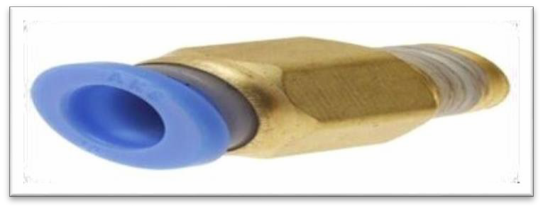
Connectors
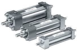
Pneumatic Cylinders
Fig.1.2 Pneumatic Cylinders
Single Acting Cylinder
Double Acting Cylinder
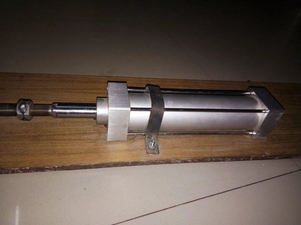
Hydraulic Cylinder
Fig. 1.3 Hydraulic Cylinder
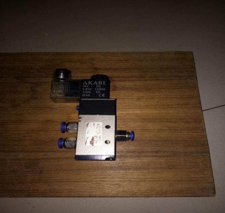
SOLENOID VALVE
One of the important parts of a pneumatic system is the direction valve. To control the direction of air flow in the pneumatic system is commonly known as DCV. The position of its internal movable parts is changed by the directional valve. To operate quickly, to reduce the manual effort and to modify the machine to operate automatically with the help of solenoid valve. An electrical device which converts electrical energy into straight line motion and force is known as solenoid. To operate mechanical operation which results in operating the valve, mechanism, solenoids are used. Type of solenoid may be push or pull. The plunger is pushed when the solenoid is energized electrically is called push type solenoid. The plunger is pulled when the solenoid is energized is called pull type solenoid. The parts of solenoid should be remembered to recognize the parts which is faulty.
Coil (Electromagnetic):
Frame
Solenoid Plunger
The mover mechanism of the solenoid is solenoid plunger. Steel laminations are used to made plunger, which are riveted together under high pressure then there will be no movement of the lamination with respect to each other. Pin hole is placed on the top of the plunger, for making a connection to some device. Movement of plunger is carried by a magnetic force in one direction and with spring action it returns to the original position. Covers are provided by solenoid operated valves over either the solenoid or the entire valve. Covering of solenoid protects the solenoid from dirt and other foreign matter, and protects the actuator.
Non-Return Valve
Valve which allows fluid (liquid or gas) to flow through it in only one direction is known as non-return valve. Two-port valves are provided in the check valves which means one valve for fluid to enter and other valve to leave the fluid. Several types of check valves are used in an extensive variety of applications in the valves. For common household items, check valves are often used. They are available in a broad range of sizes and costs. Check valves are usually very simple, small, or inexpensive check valves which work automatically and most of them are not controlled by a person or any external control. Plastics or metals are used to made the bodies (external shells) of most check valves.
Flexible Hoses
Connectors
Two types of connectors are used in this system viz. hose connectors and reducer. An adoptee hose nipple and cap nut are consisting in the hose connectors. Brass (or) aluminum (or) hardened pneumatic steel are used to made these types of connectors.
Base
ADVANTAGES:
Advantages of Hydraulics
Maximum power transmission is possible as because oil does not absorb any of the supplied energy. Due to incompressibility, high loads and forces can be resisted. The hydraulic fluid is basically incompressible, which results into a minimum of vibrations.
Advantages of Project
Pneumatic water pump has more advantages than other the pumps which are similar in size.
Efficiency is high
Positive displacement pump is fully efficient
LIMITATIONS
When compared to other device, efficiency is less.
Working of unit is affected by the leakage of air.
APPLICATIONS
LITERATURE REVEIW
The word ‘pneumatic’ originates from Greek and means breather wind. The study of air movement and its phenomena is known as pneumatic. To driving and controlling of machines and equipment is the application of air as working medium is pneumatics. To carry out the simplest mechanical tasks, pneumatics is used when time permits. Recently in automation technology, development of pneumatic technology has important role. To suit the capacity of system, it works on a supply of compressed air which should be available in adequate quantity and pressure. At the point when the pneumatic systems are being embraced just because, anyway it wills without a doubt the vital arrangement with the subject of compressed air supply. The key piece of any facility for supply of compressed air is by methods utilizing reciprocating compressor. A machine which takes air at some pressure and delivers at high pressure is known as compressor. Air at inlet conditions are specified as atmospheric pressure and ambient temperature is the total amount of air that compressed and delivered by the compressor. The first research on the compressibility of the air was done by Robert Boyle in 1962. On research, he found that the product of pressure and volume of a certain amount of gas is inversely proportional. Mathematically, it is described as PV = C or P1V1=P2V2.
SELECTION OF PNEUMATICS
The replacement of manual exertion by mechanical power is extensively characterized as mechanization. For low cost mechanization, pneumatics is a good medium especially for consecutive or repetitive actions. Numerous industries and plants have already installed a compressed air system in their premises, which is equipped for giving required energy and the control system (similarly pneumatic control systems might be monetary and can be beneficially applied to different types of power energy). The main benefit of all pneumatic system is typically financial and effortlessness to decreasing the maintenance at a low level. In terms of safety also, it provides better advantages.
PRODUCTION OF COMPRESSED AIR
POSITIVE DISPLACEMENT COMPRESSOR
The most commonly utilized system for compressed air plant and has demonstrated exceptionally effective is known as positive displacement compressor. It helps in supplying air for pneumatic control systems.
The types of positive compressor are as follows:
Reciprocating Compressors
Fig. 1.8 Working of Reciprocating Compressor
In this type of compressor, moving piston is enclosed by the chamber bore. Similar to the piston in a car engine, crankshaft of the compressor rotates and then piston moves in the cylinder. A lower atmospheric pressure in the piston chamber is created by the pulling down the piston which increases the volume in the chamber. This change in pressure causes air to enter via the inlet valve. When air pressure increases, piston forces upward which reduces the volume of air that results air to move outside from outlet valve. Multi-stage compressors with inter coolers has been established, to avoid an extreme rise in temperature. High pressure can be generated by multi-stage compressor than single-stage compressor. Two-stage compressor is most common type of compressor. Reciprocating compressors are the most common type of compressor utilized for either stationary or portable operation. It has the sizes available from the smallest capacities to deliver more than 500 m³/min. Air pressure can be of 6 bar machines which discharges a pressure up to 15 bar in a single-stage compressor. With three and four stage compressor, discharge pressure can be obtained in the range of 250 bar. For pneumatic applications, single-stage and two-stage compressor are appropriate as the discharge pressure exceeds 6 bar two-stage compressor are preferred because it can accomplish the performance match with single-stage machine at lower costs per driving energy in the range.
SELECTION OF COMPRESSOR:
CHAPTER - 2
INTRODUCTION
DESIGN OF THE PROCESS
Base
Solenoid Valve
Piston
Base
Solenoid Valve
It is a positional control valve of size 2X3 which receives the compressed air from the compressor and according to the signal it sends to the cylinder block according to the timing device. It supplies air to the front end during one position while supplies air to the rear end during the next position.
Flexible Hoses
It is the connector between the solenoid and the cylinder block. Hoses takes up the high pressure which are made of in layer of elastomer or synthetic rubber and fabric braided. It should be enclosed inside a protective sleeve when the hose is subjected to rubbing.
DEVELOPMENT OF THE PROCESS
Welding
Gas Tungsten Arc Welding
Electro Slang Welding
Electric Resistance Welding
Fig 2.1 Electric Resistance Welding
DETAILS OF ACTUAL MECHANICAL SUBPARTS
Pneumatic Cylinder
Pneumatic Cylinder
A mechanical device that uses the power of compressed gas to produce force in a reciprocation linear motion is known as pneumatic cylinder. Similar to hydraulic cylinders, Pneumatic cylinders also utilize the stored potential energy of a fluid, which is compressed air and then convert it into kinetic energy as the air expands to reach atmospheric pressure. This expanded air forces a piston to move in the desired direction. The force exerted on the object to move is transferred by piston which is a disc or cylinder, and the piston rod. Preference to use the pneumatic systems is given by engineers because they are cleaner, quieter and does not require large amount of space for storing fluid.
Single Acting Cylinder
Double Acting Cylinders
Solenoid Valve
Fig 2.3 Solenoid Valve