
Cos sin sin sin note fig
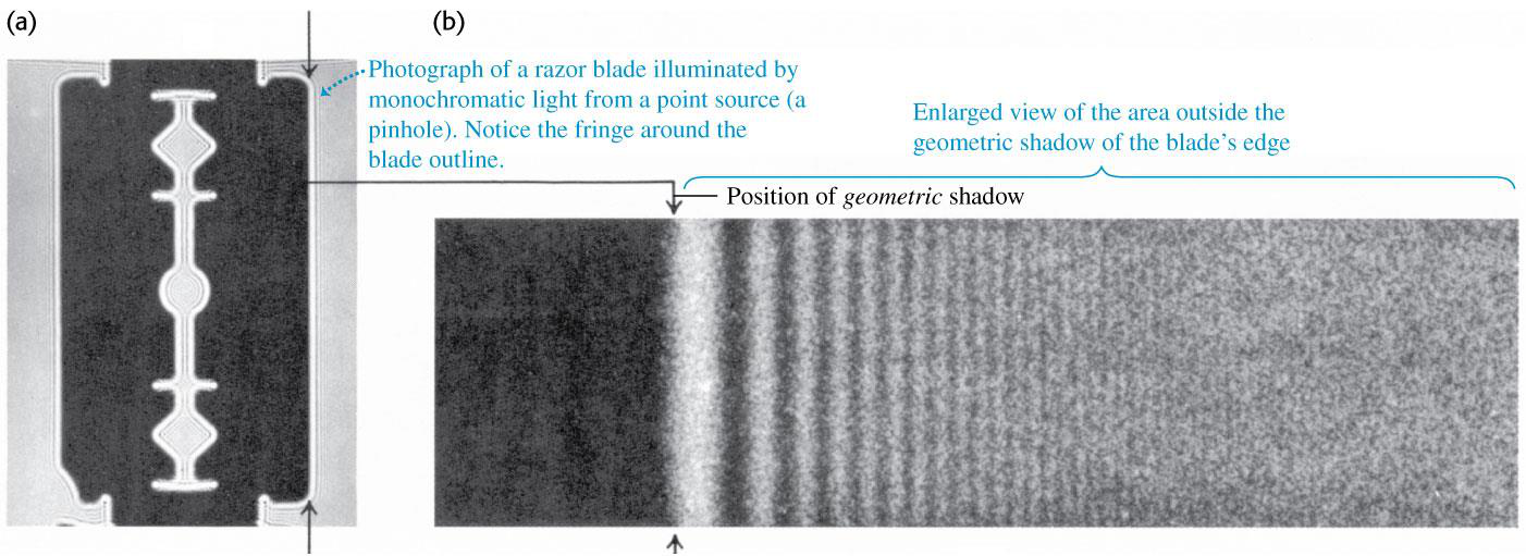
•Example: Brilliant colours seen in the light reflected from a compact disc (CD). •Diffraction can be explained using Huygen’s principle.
Classification of diffraction patterns: Fresnel Diffraction and Fraunhofer Diffraction
•Fresnel Diffraction: When the source and the screen are relatively close to the obstacle forming diffraction pattern.
•Consider the diffraction pattern formed by plane-wave monochromatic light when it emerges from a long, narrow slit (Fig. 36.2).
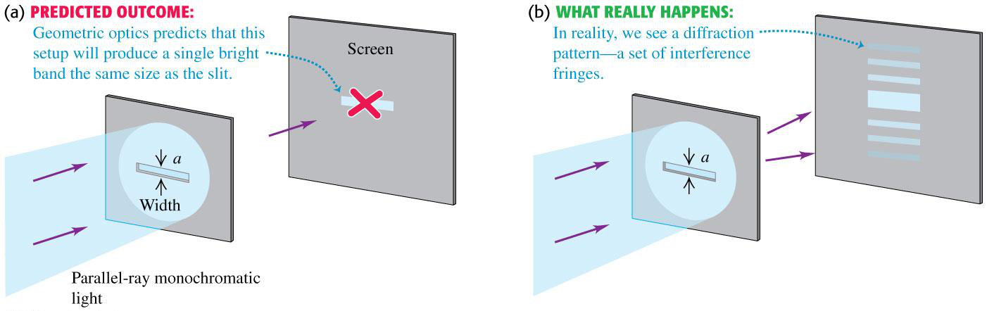
•The smaller the width of the slit, the broader is the diffraction pattern.
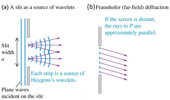
•Fig. 36.3 shows the side view of the set-up in Fig. 36.2.
2
𝑎
•The difference in the path length to point P is 2sin 𝜃. Here a
is the slit width and 𝜃is the angle from the horizontal.
•Suppose this path difference is 𝜆/2 . The light from these two points, arrive at P with opposite phase and thus cancel each other.
Condition for a dark fringe:
so small that sin 𝜃 ≈ 𝜃. Use this condition to rewrite Eq. (36.2):
4
Ans: positions of no sound with respect to centerline are 𝜃 = ±15.9°, ±33.4°, ±55.6°
36.3 Intensity in Single Slit Diffraction Pattern
•Intensity at P is proportional to 𝐸𝑃 2.
•At point O (Fig. 36.6a), where θ = 0° and for 𝑥 ≫ 𝑎, there are negligible path differences and the phasors from all the wavelets are in phase.
•Now consider point P (Fig. 36.6a), due to differences in path length, there are phase differences between wavelets coming from adjacent strips. The phasor diagram is shown in Fig. 36.6c. The vector sum of these phasors is shown by 𝐸𝑃, the amplitude of resultant electric field at P.
•Angle 𝛽, is the total phase difference between wave from the top strip with respect to the wave received at P from the bottom strip.
•Centre C is found by drawing perpendiculars at A and B and they meet at C.
•From geometry, angle ACB = β.
| sin(𝛽/2) | (Eq. 36.5) | |
|---|---|---|
| 𝐸𝑃 = 𝐸0 | 𝛽/2 |
•Recall the relationship between phase difference and path difference, we have
𝛽 = 2𝜋
𝜆𝑎 sin 𝜃 (Eq. 36.7)
| 𝐼𝑃 = 𝐼0 [ | 𝜆 sin 𝜃 |
] |
|
(Eq. 36.8) |
|---|
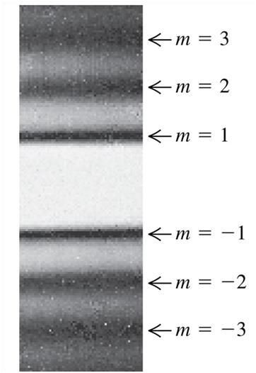
•Also, the peak intensity decreases rapidly as we go away from centre of the pattern.•Position of dark fringes can be calculated from the expression of intensity also, I=0
sin 𝜃 = 𝑚𝜆 𝑎 𝑚 = ±1, ±2, ±3 …
Intensity maxima in Single Slit Pattern
•From Eq. (36.6), the position of intensity maxima correspond to the
points where 𝛽 = ±𝜋, ±3𝜋, ±5𝜋, i.e.
•Intensity values for the side maxima may be calculated from Eq. (36.6).
•The actual intensities for 1st, 2nd and 3rd maxima around central maxima are:
| 0.0472𝐼0, | 0.0165𝐼0, |
|---|
•Thus, for a given wavelength, the spread of pattern is inversely proportional to the slit width a.
•Fig. 36.8 shows the Intensity vs. 𝜃 for slit widths, (a)𝑎 = 𝜆, (b) 𝑎 = 5𝜆, (c) 𝑎 = 8𝜆
•As a becomes bigger and bigger in comparison to λ, the fringe pattern becomes narrower,
Fig. 36.8(b) and (c).
minima of equal intensity and spacing as per Young’s Double slit experiment.
•When slits have finite width, the peaks in two-slit interference pattern are modulated by the
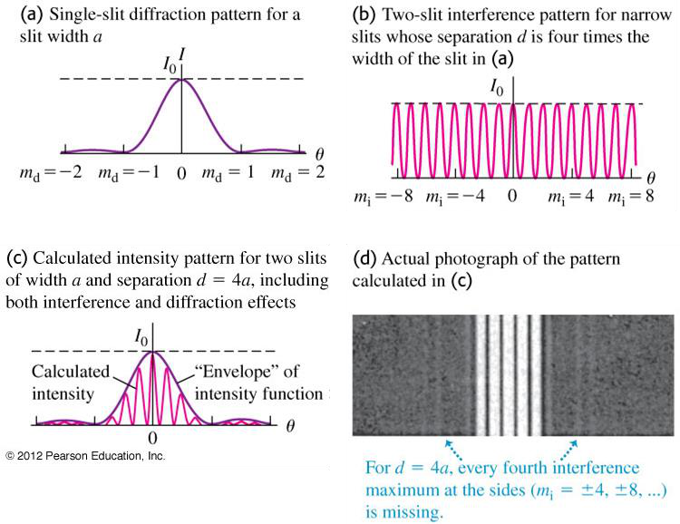
Figure 36.9 Intensity pattern for 2 slits of finite width
36.9a
•Fig. 36.9c shows the pattern from two slits with width 𝑎 and separation
𝑑 = 4𝑎.
•The effect of the finite width of the slits is to superimpose two patterns, i.e., to multiply two intensities at each point.
Ans: (a) 𝑑/𝑎 = 3, (b) 2 fringes
Example 4
10
Diffraction from Several Slits
•Condition of Constructive Interference for rays at an angle 𝜃 to the normal that arrives P:
𝑑 sin 𝜃 = 𝑚𝜆 (𝑚 = 0, ±1, ±2, ±3 … ) (Eq. 36.10)
11
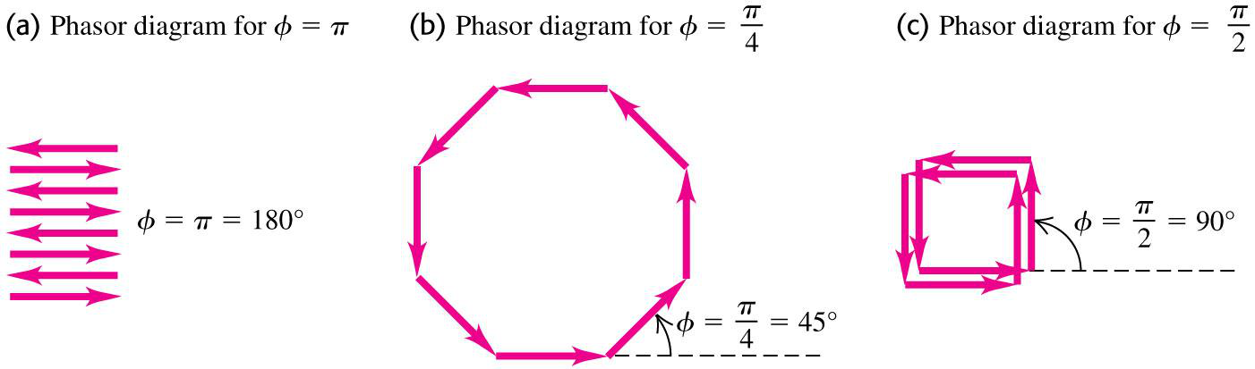
•If the phase difference 𝜙 between two slits is slightly different from a multiple of 2𝜋, the waves from the adjacent slits 1 and 2 will only be slightly out of phase but the phase difference between slits 1 and 3 will be greater, that between 1 and 4 will be greater still, and so on and so forth.
•This leads to partial cancellation of angles for a maximum, giving the narrow maxima in Fig. 36.12b.
Figure 36.12
Intensity patterns for different number of slits
•Actual grating may contain several thousand slits.
•The spacing 𝑑 between centers of adjacent slits is called grating spacing.
Figure 36.13 Diffraction grating
𝑑 sin 𝜃 = 𝑚𝜆 (𝑚 = 0, ±1, ±2, ±3 … ) (Eq. 36.11)
•The rainbow-coloured reflections that are seen on the surface of a
CD-ROM are reflection grating effect (Fig. 36.14). 
•If light of wavelength 𝜆 is incident normally on a
reflection grating with grating spacing 𝑑 between
adjacent ridges or grooves, the reflected angles at which intensity
maxima occurs is given by Eq. (36.11).
(a) the number of slits per centimeter for the grating.
(b) the angular location of the first order and second order bright bands. (c) Will there be a 4th order bright band? Explain.
(b)In the first-order spectrum, maximum for two different wavelengths are separated on the screen by 3.00 mm. What is the difference in these wavelengths?
Ans: (a) Yes. (b) 𝜆2 − 𝜆1 = 13.33 nm
Example 2
|
|---|
sin 𝜃 = 𝑚𝜆 𝑎 , (𝑚 = ±1, ±2, ±3, … )
Relation between wave velocity 𝑣, wavelength 𝜆 and wave frequency 𝑓 is:
| 𝑚 | 1 | 2 | 3 | 4 |
|---|---|---|---|---|
| 𝜃 | ±15.9° | ±33.4° | ±55.6° | Not possible |
Thus, the positions of no sound with respect to centerline are 𝜃 = ±15. 90, ±33. 40, ±55. 60.
Example 3
(b)In the case considered in (a), how many fringes are contained within first diffraction
maximum on one side of central maximum?
The third interference maxima coincides with first diffraction minimum at an angle θ1 .
Condition of first Diffraction minimum is
Let mth interference maximum coincides with second diffraction minimum.
Divide (4) by (3): 𝑚 = 6
Thus third interference maximum coincides with first diffraction minimum and 6th
16
An interference pattern is produced by light of wavelength 580 nm from a distant source incident on two identical parallel slits separated by distance (between centers) of 0.53 mm.
𝑑 sin 𝜃 = 𝑚𝜆 ⟹ sin 𝜃 = 𝑚𝜆
𝑑Angular Position 𝜃1 of first order interference maximum, 𝑚 = ±1 is given by
sin 𝜃2 = ± 2 × 𝜆 𝑑
= ± 2(580 × 10−9)
0.53 × 10⁻³
| (b) | ⟹ 𝜃2 = ± sin−1(2 × 580 × 10−6 0.53 | ||||
|---|---|---|---|---|---|
| 𝐼𝑃 = 𝐼0 cos2(𝜙 2) [sin(𝛽/2) | |||||
|
|
||||
Ans: (a) 4790cm-1, (b) 𝜃1 = 19.05°, 𝜃2 = 40.54°, (c) No
Solution:
Condition of Diffraction Grating maxima:
𝑑 sin 𝜃 = 𝑚𝜆 (a) Separation between 2 slits:
| (b) |
|---|
Angular location of 2nd order bright fringe, 𝜃2 is given by:
18
Visible light passes through a diffraction grating that has 900 slits/cm and the interference pattern is observed on a screen that is 2.5 m from the grating.
1
Grating has 900 slits/cm, 𝑑 = 90000 m
(a) Condition of Diffraction Grating maxima :
= 0.0495 ⟹ 𝜃 = 0.0495 rad
Thus sin 𝜃 = 𝜃 is a safe approximation for visible light and small 𝜃.
| 𝑑 sin 𝜃1 = 𝜆1 | 𝑑 sin 𝜃2 = 𝜆2 | |
|---|---|---|
| 𝑦 | ||
| 2.5 | ||
Then we have
| 𝑑 | 𝑦1 2.5= 𝜆1 |
𝑑 |
|
|||
|---|---|---|---|---|---|---|
| 1 | ||||||
| 𝜆2 − 𝜆1 = | 90000 | 2.5 | ||||