
Open loop system for the speed control of dc motor
Contents
The BODE plot for the DC motor control 14
Stability check by Routh-Hurwitz stability criterion: 17
Task 1
Introduction
Open Loop system for the speed control of DC motor
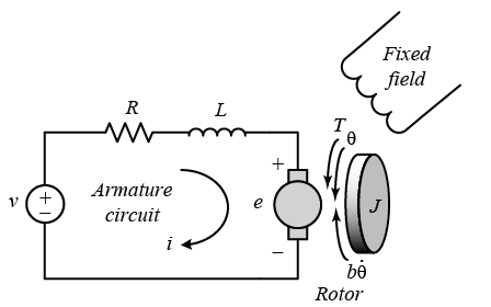
The physical set-up
The DC system is the most common actuator which is applicable in control systems. The DC motor is very critical in terms of the provision of the rotary motion. This is effectively coupled with drams, wheels or cables. The following diagram is the equivalent circuit for the DC motor armature control.
$$V - K\frac{d\theta}{dt} = L\frac{di}{dt} + Ri\ldots.(2)$$
The Laplace transformation for the above two equations were obtained as follows
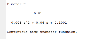
$$\frac{V(s) - Ks\theta(s)}{Ls + R}\left( Js^{2} + bs \right)(Ls + R)\theta(s) + K^{2}s\theta(s) = \frac{\left( Js^{2} + bs \right)\theta(s)}{K} = KV(s)s\theta(s)\left\{ \left( Js^{2} + bs \right)(Ls + R) + K^{2} \right\} = KV(s)\frac{s\theta(s)}{V(s)} = \frac{K}{\left( Js^{2} + bs \right)(Ls + R) + K^{2}}\frac{\overset{˙}{\theta}(s)}{V(s)} = \frac{K}{\left( Js^{2} + bs \right)(Ls + R) + K^{2}}\frac{\overset{˙}{\theta}(s)}{V(s)} = \frac{0.01}{(0.01s + 0.1)(0.5s + 1) + {0.01}^{2}}\frac{\overset{˙}{\theta}(s)}{V(s)} = \frac{2}{(s + 9.997)(s + 2.003)}$$
So, The transfer function of the speed control of the DC motor.
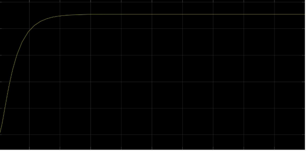
The step response for both the open loop and the close loop system is effectively shown below.
The MATLAB code
% J is the moment of inertia experienced from the motor control
b = 0.1;
L = 0.5;
% Refers to the inductance
The state space
analysis 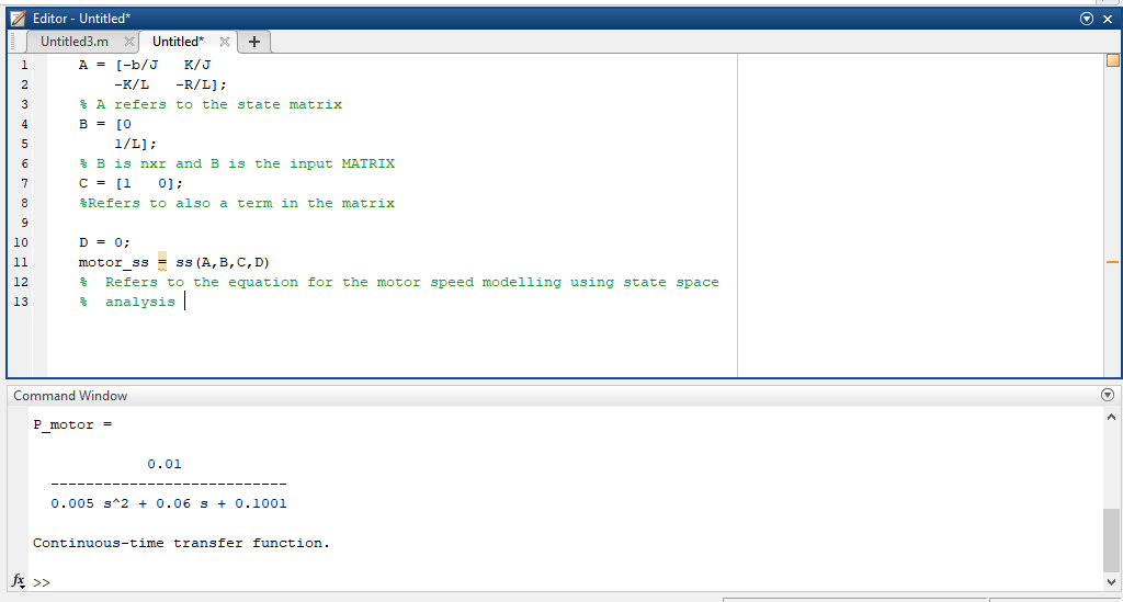
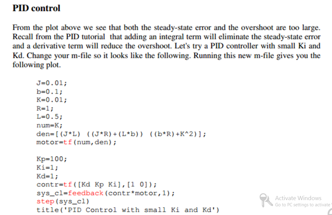
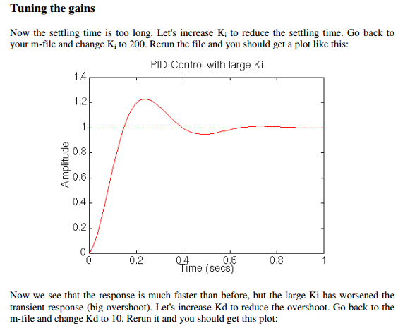
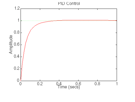
The P, PI, PD and the PID control of the DC controlled motor system
The PID Control description for the DC motor control is effective shown in the following analysis.
Conclusion:
Task 2
Introduction
The BODE plot for the DC motor control
% J is the moment of inertia experienced from the motor control
b = 0.1;
L = 0.5;
% Refers to the inductance
grid
title('Bode Plot of the Original Plant')
Stability check by Routh-Hurwitz stability criterion:
Closed loop transfer function;
$$G(s) = \frac{1}{1 + G_{motor}(s)C(s)}$$
The use of Laplace transforms to basic mechanical and electrical systems as in Fig 2.0 & Fig 3.0.
Fig 2.0
Transfer function;
$$\frac{X(s)}{F(s)} = \frac{1}{{ms}^{2} + bs}$$
The Laplace transform=$\frac{I(s)}{V(s)}\ and\ assuming\ zero\ initial\ conditions;\ $
$$\frac{I(s)}{V(s)} = \frac{1}{R + Ls + \frac{1}{Cs}}$$
Conclusions
References
Syukriyadin, S., Syahrizal, S., Mansur, G., & Ramadhan, H. P. (2018, May). Permanent magnet DC motor control by using arduino and motor drive module BTS7960. In IOP Conference Series: Materials Science and Engineering (Vol. 352, No. 1, p. 012023). IOP Publishing.
Michurin, R. A., & Schagin, A. (2018, January). Increase the accuracy of the DC motor control system with a linear-quadratic regulator. In 2018 IEEE Conference of Russian Young Researchers in Electrical and Electronic Engineering (EIConRus) (pp. 1746-1749). IEEE.