
Procedure
Physics 121A – 018
Professor Qin Li
If there is no change in current then di/dt=0 and the force across the inductor is 0. Current is constant if the switch is in any position A or B. If the force E, exists then the current is constantly changing. When the switch is moved to A position, we use Kirchhoff’s Law of voltages:
V0 – iR- L$\frac{di}{dt}$ =0
When we take the natural log of both sides:
ln[1- $\frac{i(t)}{i0}$]= $\frac{- R}{L}t$
The solution to equation 6 is
i(t)=($\frac{V0}{R})e^{- t/\tau}$, where τ=L/R is the circuit time constant. Since the voltage across the inductor is εL=-L$\frac{di}{dt}$
Lab computer with capstone software installed
850 universal interface
Digital multimeter
LCR meter
Setup
Plug a voltage probe into the Analog Inputs port A. This will be a Voltage Channel A in the measurement. Connect the black plug of the probe to the end to the resistor and the red one of the probe to the other end of the resistor which is connected to the inductor.
Procedure
Measure the inductance and resistance of the inductors used in this lab using the LCR meter to measure the exact values of inductor and a digital multimeter to measure the exact value of resistance of inductors and resistor. Total resistance Rt in the loop is then Rtotal=Rinductor+Rresistor and the time constant τ = L/Rtotal
Open “Lab 218 RL Circuit” file in “Physics 121A Lab Experiments” folder on Desktop.
Go to the “Measurement” page on the screen that you just opened and select “850 Output 1” in the signal generator. The signal generator will be the alternating voltage source with a square waveform in this experiment.
Chose data which you want to analyze.
Click “Calculator” tool at the right side of the screen. Insert values for the resistor and maximum voltage that we calculated. Click “Accept.”
| Experimental | ||
|---|---|---|
| Inductor | Inductance | Resistance |
| (mH) | (Ω) | |
| Solenoid | 6.7 | 1.7 |
| Current Loop | 20.1 | 6.8 |
Rtotal, solenoid = 1.7+9.7=11.4Ω
Rtotal, current loop = 6.7+9.7=16.5Ω
Plot of Time vs Voltage for Solenoid
Plot of Time vs ln(i(t)/i0) and ln(1-i(t)/i0) (Solenoid)
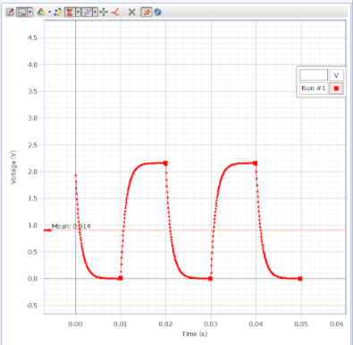
Plot of Time vs Voltage for Current Loop
Vmax=2.150 V
Plot of Time vs ln(i(t)/i0) and ln(1-i(t)/i0) (Current Loop)
Error
εL, current loop =$\ \frac{23 - 20.1}{23} \times 100\%$= 12.61%
εR, solenoid =$\ \frac{1.8 - 1.7}{1.8} \times 100\%$= 5.56%
In this lab, our group was able to study an RL circuit and the current that flows through it. We use the LoggerPro software to record data for the flowing current, and obtained values which we compared to the theoretical values we calculated. In the process however we did come across some error, which can be attributed to multimeter reading errors, and equipment errors. In conclusion, despite any errors that may have occurred, we were able to verify the equations surrounding RL circuits and successfully complete this experiment.