
Screen shot soft- ware produces lower quality output
Investigation into the Modelling and Control of a d.c. Motor
Deadline 18thJanuary 2020 by 23:00 (UK time)
Please include your student ID number within the report, inside the header or footer is a good way to do this on each page.
Additional Information Students are reminded about plagiarism. The University considers that plagiarism may take different forms, including, but not lim- ited to, the submission of work that is wholly or substantially the work of another, and also the submission of work that is wholly or significantly based on the work of another.
Task 1 - Modelling
A d.c. motor is to be controlled using a variety of methods. Unfortunately, the control engineer does not have any suitable transfer function model of the system as a basis for controller design. In order to tackle this problem, a simple experimental feedback test rig is constructed, and various data are collected from the system. The data is noisy and uncertain, due to limitations of the methods used to collect it.
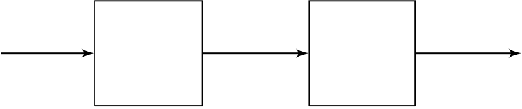
| Vin(s) | P(s) |
|---|
Position Response - Finding G1(s)
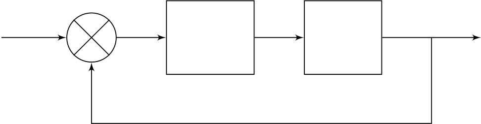
The engineer adjusts the rig, so that the motor position is controlled under feedback, with a motor represented by G1(s), and with a simple proportional gain (amplifier) in series with the motor, as shown in Figure 2. k is set to 10 for these experiments.
You may develop more than one transfer function for G1(s). However, at the end of Task 1, you should aim to take one suitable transfer function model for G1(s) forward into the remaining Tasks. The model for P(s) does not need to be taken forward.
[35 Marks]
| Page 2 of 7 |
|---|
It is known that the parameters of the production motors differ from those of the test rig version. In order to reflect some differences, you should present another motor model, G2(s) as follows: Assuming that your motor model has real-valued poles, select one motor pole location (not 0) and multiply the value of the pole by 1.x where x is the last two digits of your student registration number in reverse. Select the numerator of G1(s), and multiply it by 1.y where y is the last two digits of your student registration number.
For example if your motor model in Task 1 is found as:
Please note, the above example shows how to introduce a variation, it does not necessarily reflect an appropriate choice of structure, or of parameter values, for G1(s). Include an expression for G2(s) in your report at the start of Task 2, but do not use useful report space deriving it. I can do that! The production system is modelled as shown in the block diagram of Figure 3. Two additional gain blocks also have (identical) parameter values dependent on your student registration number, where x is defined as before.
Figure 3: Motor Position Control Block Diagram
Investigate the effects of choosing a proportional controller K(s) = k in the feedback scheme of Figure 3 and propose a suitable controller design. Please note, there is no set specification that you are required to achieve. It is up to you to choose what aspects to investigate in this Task, and to make appropriate deductions based on the requirements that you determine.
| Page 3 of 7 |
|---|
This is also an open investigation, there is no set specification to meet. Reflect on advantages and disadvantages compared to proportional control alone.
[20 Marks]
[30 Marks]
General Guidance
You are welcome to ask for advice, particularly about MATLAB commands, in Moodle. However, I am not able to offer comments on the actual work you have done, so please do not post it in Moodle.
Grading Criteria
| 70-79 |
|
| 60-69 | |
| 50-59 | |
| 40-49 |
|
| 30-39 | |
| 6 |
|
|---|
1
| 0 | 5 | 10 | 15 | 20 |
|
|---|
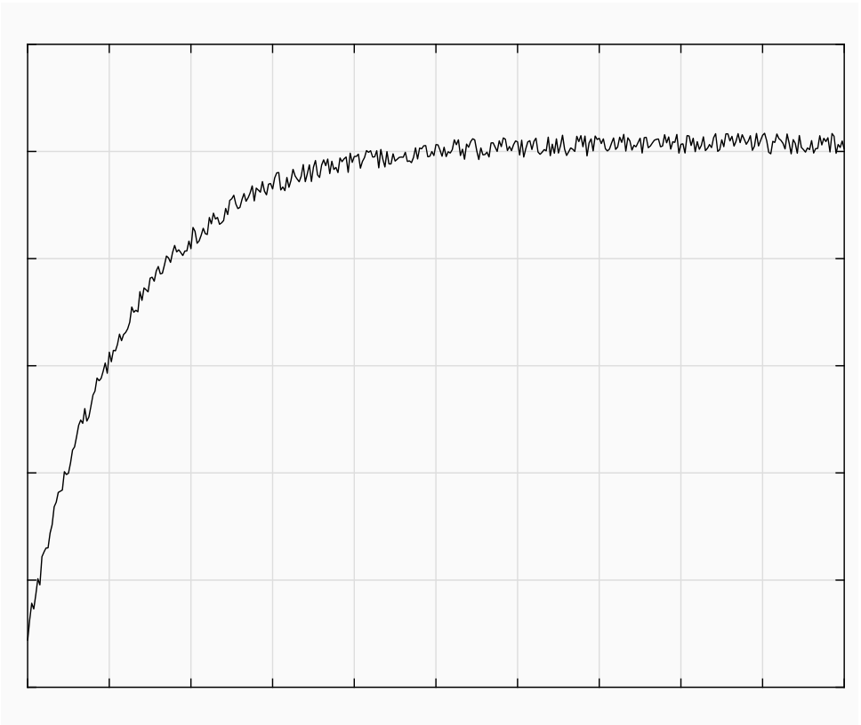
Figure 5: Task 1 - Motor Position Step Response Data
| 20 |
|---|
10
5
20 |
100 | 101 |
|---|---|---|
|
||
|
100 | 101 |
|---|---|---|
| Frequency - rad/s |
Figure 6: Task 1 - Motor Position Frequency Response Data