
Select the wind zone based the strength design wind speed
IBC®
2015 International Building Code
EFFECTIVE USE OF THE INTERNATIONAL BUILDING CODE
|
|
|---|---|
|
|
|
|
|
|
The following is a chapter-by-chapter synopsis of the scope and intent of the provisions of the International Building Code. [partial shown]
User Note: The chapters shown below are those that are highlighted in this document and provide wind resistant provisions.
2
ChapterExterior Walls. [partial shown]This chapter addresses requirements for exterior walls of buildings. Minimum standards for wall covering materials, installation of wall coverings and the ability of the wall to provide weather protection are provided. The installation of each type f wall covering, be it wood, masonry, vinyl, metal composite material, or an exterior insulation and finish system, is critical to its long-term
performance in protecting the interior of the building from the elements and the spread of fire.ChapterSpecial Inspections and Tests. Chapterprovides a variety of
procedures and criteria for testing materials and assemblies, labeling materials and assemblies and special inspection of structural assemblies. This chapter expands on the inspections of Chapterby requiring special inspection where indicated and, in some cases, structural observation. It also spells out additional responsibilities for the owner, contractor, design professionals and special inspectors. Proper assembly of structural components, proper quality of materials used and proper application of materials are essential to ensuring that a building, once constructed, complies with the structural and fire-resistance minimums of the code and the approved design. To determine this compliance often requires continuous or frequent inspection and testing.Chapterestablishes standards for special inspection, testing and reporting of the work to the building official.
ChapterSteel. Chapterprovides the requirements necessary for the design and construction of structural steel (including composite construction), cold-formed steel, steel joists, steel cable structures and steel storage racks. The chapter specifies appropriate design and construction standards for these types of structures. It also provides a road map of the applicable technical requirements for steel structures. Because steel is a noncombustible building material, it is commonly associated with Types I and II construction; however, it is permitted to be used in all types of
construction. Chapterrequires that the design and use of steel materials be in accordance with the specifications and standards of the American Institute of Steel Construction, the American Iron and Steel Institute, the Steel Joist Institute, and the American Society of Civil Engineers.ChapterWood. This chapter provides minimum requirements for the design of buildings and structures that use wood and wood-based products. The chapter is organized around three design methodologies: allowable stress design (ASD), load and resistance factor design (LRFD) and conventional light-frame construction. Included in the chapter are references to design and manufacturing standards for various wood and wood-based products; general construction requirements; design criteria for lateral force-resisting systems and specific requirements for the application of the three design methods. In general, only Type III, IV or V buildings may be constructed of wood.
reinforced gypsum concrete. These represent the most common interior and exterior finish materials in the building industry. This chapter primarily addresses quality-control-related issues with regard to material specifications and installation requirements. Most products are manufactured under the control of industry standards. The building official or inspector primarily needs to verify that the appropriate product is used and properly installed for the intended use and location. While often simply used as wall and ceiling coverings, proper design and application are necessary to provide weather resistance and required fire protection for both structural and nonstructural building components.
ChapterPlastic. [partial shown]The use of plastics in building construction and components is addressed in Chapter This chapter provides standards addressing foam plastic insulation, foam plastics used as interior finish and trim, and other plastic veneers used on the inside or outside of a building. Plastic siding is regulated by Chapter Sectionsthroughaddress the use of light-transmitting plastics in various configurations such as walls, roof panels, skylights, signs and as glazing.
5
AppendixSigns. Appendixgathers in one place the various code standards that regulate the construction and protection of outdoor signs. Whenever possible, the appendix provides standards in performance language, thus allowing the widest possible application.
[A] 107.2.4 Exterior wall envelope. Construction documents for all buildings shall describe the exterior wall envelope in sufficient detail to determine compliance with this code. The construction documents shall provide details of the exterior wall envelope as required, including flashing, intersections with dissimilar materials, corners, end details, control joints, intersections at roof, eaves, or parapets, means of drainage, water-resistive membrane and details around openings.
The construction documents shall include manufacturer's installation instructions that provide supporting documentation that the proposed penetration and opening details described in the construction documents maintain the weather resistance of the exterior wall envelope. The supporting documentation shall fully describe the exterior wall system that was tested, where applicable, as well as the test procedure used.
6
EXTERIOR WALL COVERING. A material or assembly of materials applied on the exterior side of exterior walls for the purpose of providing a weather-resisting barrier, insulation or for aesthetics, including but not limited to, veneers, siding, exterior insulation and finish systems, architectural trim and embellishments such as cornices, soffits, facias, gutters and leaders.
[BS] MAIN WIND FORCE-RESISTING SYSTEM. An assemblage of structural elements assigned to provide support and stability for the overall structure. The system generally receives wind loading from more than one surface.
[BS] RISK CATEGORY. A categorization of buildings and other structures for determination of flood, wind, snow, ice, and earthquake loads based on the risk associated with unacceptable performance.
[BS] SUBSTANTIAL IMPROVEMENT. Any repair, reconstruction, rehabilitation, alteration, addition or other improvement of a building or structure, the cost of which equals or exceeds 50 percent of the market value of the structure before the
improvement or repair is started. If the structure has sustained substantial damage, any2 The "[BS]" indicates that the Structural Code Development Committee is responsible for this portion of the code.
[BS] SUBSTANTIAL STRUCTURAL DAMAGE. A condition where one or both of the following apply:
1. The vertical elements of the lateral force-resisting system have suffered damage such that the lateral load carrying capacity of any story in any horizontal direction has been reduced by more than 33 percent from its predamage condition.
For Risk Category II buildings and structures and Risk Category III buildings and structures, except health care facilities, the wind-borne debris region shall be based on Figure 1609.3.(l). For Risk Category IV buildings and structures and Risk Category Ill health care facilities, the wind-borne debris region shall be based on Figure 1609.3(2).
[BS] WIND SPEED, Vult. Ultimate design wind speeds.
423.1.1 Scope. This section applies to the construction of storm shelters constructed as separate detached buildings or constructed as safe rooms within buildings for the
8
User Note: Highlights of ICC 500-2014, ICC/NSSA Standard for the Design and Construction of Storm Shelters can be found at https://www.fema.gov/media-
library/assets/documents/110209
423.3 Critical emergency operations. In areas where the shelter design wind speed for tornados in accordance with Figure 304.2(1) of ICC 500 is 250 MPH,911 call stations, emergency operation centers and fire, rescue, ambulance, and police stations shall have a storm shelter constructed in accordance with ICC 500.Exception: Buildings meeting the requirements for shelter design in ICC 500.
Exception:
1. Group E day care facilities.
User Note: ASTM D 3679 includes wind resistance criteria.
[BS] 1405.14 Vinyl siding. Vinyl siding conforming to the requirements of this section and complying with ASTM D 3679 shall be permitted on exterior walls of buildings located in areas where Vasd as determined in accordance with Section 1609.3.1 does not exceed 100 miles per hour (45 m/s) and the building height is less than or equal to 40 feet (12 192 mm) in Exposure C. Where construction is located in areas where Vasd as determined in accordance with Section 1609.3.1 exceeds 100 miles per hour (45 m/s), or building heights are in excess of 40 feet (12 192 mm), tests or calculations indicating compliance with Chapter 16 shall be submitted. Vinyl siding shall be secured to the building so as to provide weather protection for the exterior walls of the building.
1407.5 Approval. Results of approved tests or an engineering analysis shall be submitted to the building official to verify compliance with the requirements of Chapter 16 for wind loads.
SECTION 1408
EXTERIOR INSULATION AND FINISH SYSTEMS (EIFS)1504.1.1 Wind resistance of asphalt shingles. Asphalt shingles shall be tested in accordance with ASTM D 7158. Asphalt shingles shall meet the classification
requirements of Table 1504.1.1 for the appropriate maximum basic wind speed. Asphalt shingle packaging shall bear a label to indicate compliance with ASTM D 7158 and the required classification in Table 1504.1.1.Exception: Asphalt shingles that are not included in the scope of ASTM D 7158 shall be tested and labeled to indicate compliance with ASTM D 3161 and the required classification in Table 1504.1.1.
1504.2.1.2 Wind tunnel testing. Where concrete and clay roof tiles do not satisfy the limitations in Chapter 16 for rigid tile, a wind tunnel test shall be used to determine the
11
Exceptions:
1. Metal roofs constructed of cold-formed steel shall be permitted to be designed and tested in accordance with the applicable referenced structural design standard in Section 2210.1.
Table 1504.8. Provides the maximum allowable mean roof height permitted for buildings with aggregate on the roof areas outside of a hurricane-prone region
12
Exception: As an alternative, adhered underlayment complying with ASTM D 1970 shall be permitted.
User Note: Similar high wind underlayment attachment is given for tile (1507.3.3.3), metal panels (1507.4.5), metal shingles (1507.5.3.1, roll roofing (1507.6.3.1), slate (1507.7.3.1), wood shingles (1507.8.3.1), wood shakes (1507.9.3.1) and photovoltaic shingles (1507.17.4.1).
Table 1504.1.1. Provides ASTM classifications for asphalt shingles.
[BS] 1510.7.1 [Photovoltaic panels and modules.] Wind resistance. Rooftop-mounted photovoltaic panels and modules shall be designed for component and cladding wind loads in accordance with Chapter16 using an effective wind area based on the dimensions of a single unit frame.
User Note: This section addresses reroofing. The wind load/resistance criteria for reroofing are the same as for new construction.
CHAPTER 16
STRUCTURAL DESIGN1. Subject to the limitations of Section the provisions of ICC 600 shall be permitted for applicable Group R-2 and R-3 buildings.
2. Subject to the limitations of Section residential structures using the provisions of AWC WFCM.
The wind speeds in Figuresandare ultimate design wind speeds, Vult, and shall be converted in accordance with Sectionto
14
3. The hill, ridge or escarpment is unobstructed upwind by other such topographic features for a distance from the high point of 50 times the height of the hill or 1 mile (1.61 km), whichever is greater.
1609.1.2 Protection of openings. In wind-borne debris regions, glazing in buildings shall be impact resistant or protected with an impact-resistant covering meeting the requirements of an approved impact-resistant standard or ASTM E 1996 and ASTM E 1886 referenced herein as follows:
Attachments shall be designed to resist the components and cladding loads determined in accordance with the provisions of ASCE 7, with corrosion-resistant attachment hardware provided and anchors permanently installed on the building. Attachment in accordance with Tablewith corrosion-resistant attachment hardware provided and anchors permanently installed on the building is permitted for buildings with a mean roof height of 45 feet (13 716 mm) or less where Vasd determined in accordance with Sectiondoes not exceed 140 mph (63 m/s).
2. Glazing in Risk Category I buildings, including greenhouses that are occupied for growing plants on a production or research basis, without public access shall be permitted to be unprotected.
6.2.2 Unless otherwise specified, select the wind zone based on the strength design wind speed, Vult, as follows:
6.2.2.1 Wind Zone 1—130 mph ≤ ultimate design wind speed, Vult < 140 mph.
1609.2 Definitions. For the purposes of Sectionand as used elsewhere in this code, the following terms are defined in Chapter
HURRICANE-PRONE REGIONS.
16
wind regions indicated near mountainous terrain and near gorges shall be in
accordance with local jurisdiction requirements. The ultimate design wind speeds, Vult, determined by the local jurisdiction shall be in accordance with Section 26.5.1 of ASCE 7.
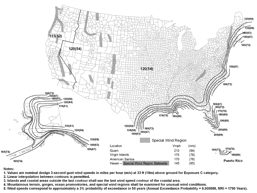
FIGURE 1609.3(2). ULTIMATE DESIGN WIND SPEEDS, Vult, FOR RISK CATEGORY III AND IV BUILDINGS AND OTHER STRUCTURE
(Equation 16-33)
where:
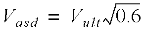
| Vult | 100 | 110 | 120 | 130 | 140 | 150 | 160 | 170 | 180 | 190 | 200 |
|---|---|---|---|---|---|---|---|---|---|---|---|
| Vasd | 78 | 85 | 93 | 101 | 108 | 116 | 124 | 132 | 139 | 147 | 155 |
For SI:1 mile per hour = 0.44 m/s.
a. Linear interpolation is permitted.
1609.4.2 Surface roughness categories. A ground surface roughness within each 45-degree (0.79 rad) sector shall be determined for a distance upwind of the site as defined in Sectionfrom the categories defined below, for the purpose of assigning an exposure category as defined in Section
Surface Roughness B. Urban and suburban areas, wooded areas or other terrain with numerous closely spaced obstructions having the size of single-family dwellings or larger.
20
by Surface Roughness B, prevails in the upwind direction for a distance of at least 1,500 feet (457 m). For buildings with a mean roof height greater than 30 feet (9144 mm), Exposure B shall apply where Surface Roughness B prevails in the upwind direction for a distance of at least 2,600 feet (792 m) or 20 times the height of the building, whichever is greater.
1609.5.1 Roof deck. The roof deck shall be designed to withstand the wind pressures determined in accordance with ASCE 7.
1609.5.2 Roof coverings. Roof coverings shall comply with Section
where:
Ma = qhCLbLLa[1.0 - GCp] (Equation 16-34)
21
GCp = Roof pressure coefficient for each applicable roof zone determined from Chapter 30 of ASCE 7. Roof coefficients shall not be adjusted for internal pressure.
Concrete and clay roof tiles complying with the following limitations shall be designed to withstand the aerodynamic uplift moment as determined by this section.
1. The roof tiles shall be either loose laid on battens, mechanically fastened, mortar set or adhesive set.
6. The exposed width of the tile shall be between 0.67 and 1.25 feet (204 mm and 381 mm).
7. The maximum thickness of the tail of the tile shall not exceed 1.3 inches (33 mm).
1. The building or other structure is less than or equal to 75 feet (22 860 mm) in height with a height-to-least-width ratio of 4 or less, or the building or other structure has a fundamental frequency greater than or equal to 1 hertz.
2. The building or other structure is not sensitive to dynamic effects.
1609.6.2 Symbols and notations. Coefficients and variables used in the alternative all-heights method equations are as follows:
Cnet = Net-pressure coefficient based on Kd [(G) (Cp) - (GCpi)], in accordance with Table
1609.6.3 Design equations. When using the alternative all-heights method, the MWFRS, and components and cladding of every structure shall be designed to resist the effects of wind pressures on the building envelope in accordance with Equation 16-35.
1609.6.4.1 Main windforce-resisting systems. The MWFRS shall be investigated for the torsional effects identified in ASCE 7 Figure 27.4-8.
1609.6.4.2 Determination of Kz and Kzt. Velocity pressure exposure coefficient, Kz, shall be determined in accordance with ASCE 7 Section 27.3.1 and the topographic factor, Kzt, shall be determined in accordance with ASCE 7 Section 26.8.
2. Where Cnet has more than one value, the more severe wind load condition shall be used for design.
1609.6.4.4 Application of wind pressures. When using the alternative all-heights method, wind pressures shall be applied simultaneously on, and in a direction normal to, all building envelope wall and roof surfaces.
3. Where applicable, the calculated pressures at discontinuities (Zone 2 or 3) shall be combined with design pressures that apply specifically on rakes or eave overhangs.
SECTION 1612
FLOOD LOADS1704.3.3 Wind requirements in the statement of special inspections. Where Sectionspecifies special inspection for wind resistance, the statement of special inspections shall identify the main windforce-resisting systems and wind-resisting components that are subject to special inspections.
1704.6.2 Structural observations for wind requirements. Structural observations shall be provided for those structures sited where Vasd as determined in accordance with Sectionexceeds 110 mph (49 m/sec), where one or more of the following conditions exist:
1705.11 Special inspections for wind resistance. Special inspections for wind resistance specified in Sectionsthrough unless exempted by the exceptions to Section are required for buildings and structures constructed in the following areas:
25
1705.11.2 Cold-formed steel light-frame construction. Periodic special inspection is required for welding operations of elements of the main windforce-resisting system. Periodic special inspection is required for screw attachment, bolting, anchoring and other fastening of elements of the main windforce-resisting system, including shear walls, braces, diaphragms, collectors (drag struts) and hold-downs.
Exception: Special inspections are not required for cold-formed steel light-frame shear walls and diaphragms, including screwing, bolting, anchoring and other fastening to components of the windforce resisting system, where either of the following applies:
2. Exterior wall covering and wall connections to roof and floor diaphragms and framing.
1709.5.2 Exterior windows and door assemblies not provided for inSection Exterior window and door assemblies shall be tested in accordance with ASTM E 330. Structural performance of garage doors and rolling doors shall be determined in accordance with either ASTM E 330 or ANSI/DASMA 108, and shall meet the acceptance criteria of ANSI/DASMA 108. Exterior window and door assemblies containing glass shall comply with Section The design pressure for testing shall
1810.3.3.1.5 Uplift capacity of a single deep foundation element.[partial shown]
Exception: Where uplift is due to wind or seismic loading, the minimum factor of safety shall be two where capacity is determined by an analysis and one and one-half where capacity is determined by load tests.
SECTION 2109
EMPIRICAL DESIGN OF MASONRY2109.1.1 [General] Limitations.[partial shown]
SECTION2211
COLD-FORMED STEEL
LIGHT-FRAME CONSTRUCTION2211.6 Lateral design. Light-frame shear walls, diagonal strap bracing that is part of a structural wall and diaphragms used to resist wind, seismic and other in-plane lateral loads shall be designed in accordance with AISI S213.
5.6. Environmental design criteria and loads (wind, rain, snow, seismic, etc.).
8. Maximum reaction force and direction, including maximum uplift reaction forces where applicable
2304.10.6 Load path. Where wall framing members are not continuous from the foundation sill to the roof, the members shall be secured to ensure a continuous load path. Where required, sheet metal clamps, ties or clips shall be formed of galvanized
28
2305.1 General. Structures using wood-frame shear walls or wood-frame diaphragms to resist wind, seismic or other lateral loads shall be designed and constructed in accordance with AF&PA SDPWS and the applicable provisions of Sectionsand
SECTION 2306
ALLOWABLE STRESS DESIGN2306.3 Wood-frame shear walls. Wood-frame shear walls shall be designed and constructed in accordance with AWC SDPWS. Where panels are fastened to framing members with staples, requirements and limitations of AWC SDPWS shall be met and the allowable shear values set forth in Tableorshall be permitted. The allowable shear values in Tablesandare permitted to be increased 40 percent for wind design. Panels complying with ANSI/APA PRP-210 shall be permitted to use design values for Plywood Siding in the AWC SDPWS.
29
2308.2.4 Ultimate wind speed. Vult shall not exceed 130 miles per hour (57 m/s) (3-second gust).
Exceptions:
Table 2308.7.5. Provides the required rating of approved uplift connectors.
SECTION2309
WOOD FRAME CONSTRUCTION MANUAL
0.6Fgw ≤ Fga (Equation 24-1)
where:
Fgw = Wind load on the glass due to ultimate design wind speed, Vult, computed in accordance with SectionFga = Short duration load on the glass as determined in accordance with ASTM E 1300.
Fg = Total load, psf (kN/m2) on glass.
S = Snow load, psf (kN/m2) as determined in Section
θ = Angle of slope from horizontal.
Exception: The performance grade rating of unit skylights and tubular daylighting devices shall be determined in accordance with Section
Fge = Nonfactored load from ASTM E 1300 using a thickness designation for monolithic glass that is not greater than the thickness of wired glass.
2404.3.2 Sloped wired glass. Wired glass sloped more than 15 degrees (0.26 rad) from vertical in skylights, sun-spaces, sloped roofs and other exterior applications shall be designed to resist the most critical of the combinations of loads from Section
Fg = Total load on the glass as determined by Equations 24-2, 24-3 and 24-4.
Fge = Nonfactored load in accordance with ASTM E 1300.
Fge = Nonfactored load in accordance with ASTM E 1300. The value for patterned glass shall be based on the thinnest part of the glass. Interpolation between nonfactored load charts in ASTM E 1300 shall be permitted.
2404.3.4 Sloped patterned glass. Patterned glass sloped more than 15 degrees (0.26 rad) from vertical in skylights, sunspaces, sloped roofs and other exterior applications shall be designed to resist the most critical of the combinations of loads from Section
where:
Fg = Total load on the glass as determined by Equations 24-2, 24-3 and 24-4.
33
where:
Fg ≤ PG (Equation 24-13)
where:
Fgo ≤ PGNe (Equation 24-15)
where:
34
where:
Wo = Outward wind force, psf (kN/m2) due to ultimate design wind speed, Vult, as calculated in SectionD = The dead weight of the glazing, psf (kN/m2) as determined in Sectionfor glass, or by the weight of the plastic for plastic glazing.
Fgi = Maximum load on the skylight determined from Equations 24-2 through 24-4 in Section
with the materials and provisions of Sectionare permitted to resist wind and seismic loads. [partial shown]
CHAPTER 26
PLASTIC1. Where the cladding manufacturer has provided approved installation instructions for application over foam sheathing and connection to a masonry or concrete substrate, those requirements shall apply.
2. For exterior insulation and finish systems, refer to Section
1. Where the cladding manufacturer has provided approved installation instructions for application over foam sheathing, those requirements shall apply.
2. For exterior insulation and finish systems, refer to Section
36
Proper allowance shall be made for expansion and contraction of light-transmitting plastic materials in accordance with accepted data on the coefficient of expansion of the material and other material in conjunction with which it is employed.
CHAPTER 31
SPECIAL CONSTRUCTIONSECTION 3108
TELECOMMUNICATION AND BROADCAST TOWERS[BS] 3108.1 General. Towers shall be designed and constructed in accordance with the provisions of TIA-222. [partial shown] In Section 2.6.6.2 of TIA 222, the horizontal extent of Topographic Category 2, escarpments, shall be 16 times the height of the
escarpment.
CHAPTER 35
REFERENCED STANDARDS
|
||
|---|---|---|
|
||
| Tensile Membrane Structures | ||
|
||
|
||
|
||
|
||
39
40
APPENDIX H
SIGNSThe provisions contained in this appendix are not mandatory unless specifically referenced in the adopting ordinance.
SECTION I105
STRUCTURAL PROVISIONS