
Semiconductor iifinal projectintroduction here you will take sample optical heart-rate data from phototransistor and design circuit order meet specifications
The power supply and input stage: includes a phototransistor and IR LED to capture the fluctuations of pressure in the blood stream.
The signal processing circuit: filters and amplifiers the circuit.
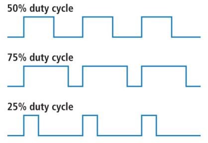 Duty cycle between 35% and
65%. Duty cycle is the ratio of pulse width to period.
Duty cycle between 35% and
65%. Duty cycle is the ratio of pulse width to period.A voltage output that is a “near” square wave between
Filtering Circuit
Again make sure that loading is minimized
Your interface circuit:
You will need to reduce source loading effects.
Amplifying circuit
Given the design requirements determine the necessary gain for your circuit
 Make one sub-circuit at a
time and monitor your signal response at each stage to ensure that
you’re meeting spec and not distorting your signal.
Make one sub-circuit at a
time and monitor your signal response at each stage to ensure that
you’re meeting spec and not distorting your signal.
Typical PPG Measurements
1N4004 Diode
Discrete Standard Resistors
An SPC design that meets specifications given to produce an appropriate output signal.
There are many ways to accomplish this through design. Some more challenging some not as challenging.