
Shown fig sin omega frac omega cos omega omega sin fig shows current
Consider a DC circuit having three resistance(R1,R2,R3) connected in series excited by a DC source V (fig-1) and a current I is circulating in circuit .
Voltage drop across resistance R1 = IR1
I=$\frac{V}{R1 + R2 + R3}$
Consider AC circuit (fig-2(a)) an electric bulb is excited by an AC source shown in fig-2(b).Rating of electric bulb is 100 watt,220volt and AC source is 220$\sqrt{2}$ sin(wt)
Circuit: Circuit is the combination of source (Depended or Independent) with active or passive elements
Circuit Elements: Circuit Elements are Resistance R , Inductor L ,Capacitor C
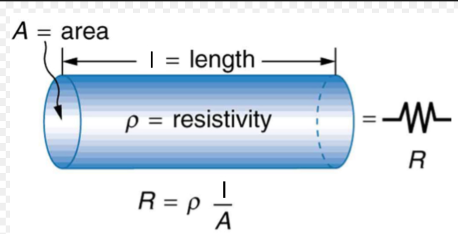
If we consider a conductor having length l and resistivity =ρ crossectional area of conductor is A
positive for conductor and Negative for semiconductor
R0 is resistance at room temperature
Capacitor:
voltage applied across capacitor =Vc
Capacitance (C) =$\frac{Q}{Vc}$ ...........................................(4)
I=$\frac{1}{R}$ ΔV
ΔV = IR....................................................(5)
Kirchhoff Law: Kirchhoff Current Law
Kirchhoff voltage Law
In above fig7 we select anode and I1,I2,I3 are the incoming current (coming to node ) and I4,I5 are outgoing current
so I1+I2+I3=I4+I5 ................................(6)
So Vs=IR1+IR2.............................................(7)
I=$\frac{Vs}{R1 + R2}$
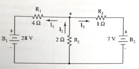
Apply KCL at node a
Va=8 volt
I 1=$\frac{Va - 28}{4}$ = -5 A , P1=25* 4 = 100 watt
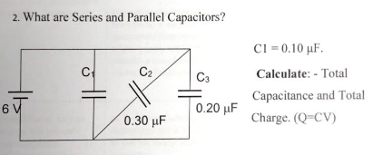
In above fig all three capacitor are connected in parallel
Q= CeqV= 0.60 μF*6 volt=0.36 Coulombs
Power:
Apparent Power = Active Power + j Reactive Power
Series and Parallel circuit: Consider fig - Resistance R1 ,R2,R3 are connected in series excited by a DC supply Voltage V , if we apply KVL in given loop .
Comparing above Equation with Ohms law
V=I Req
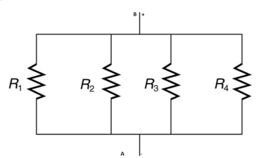
Consider three resistance connected in parallel as show in fig -11 terminal A&B are connected to Dc battery source V, Equivalent resistance circuit will be
Electromagnetism:
Electromagnetic field is a type of energy , or energy with position. A field is a set of lines surrounding the body, however these lines do not exist, they are strictly a mathematical construct to describe motion. Fields are used in electricity, magnetism, gravity .
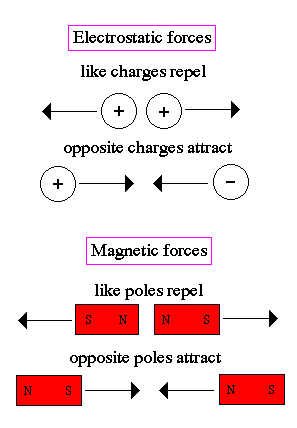
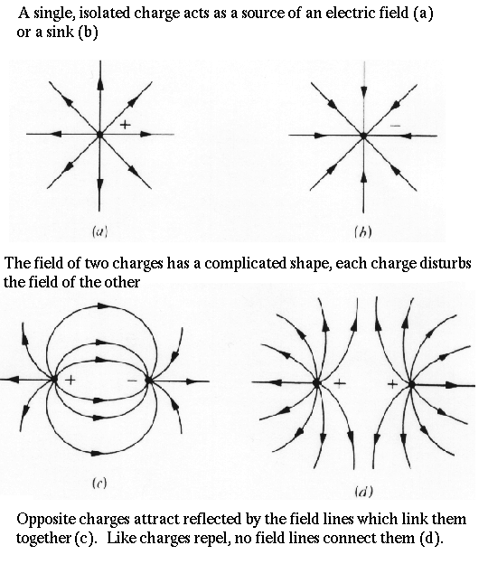
Fig 13(a) (b)
⌀=BA
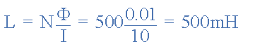
If we use more than one loop or coil of N turns a the flux flowing
through the N turns is simply N times that flowing through the single
loop(NΦ). point.
Therefore: Flux linkage = N ⌀
=NBA
Flux density is number of magnetic lines of flux passing throguh a unit area its unit is tesla or weber / square meter Denoted by B
Reluctance and permeability
Permeability is the measure of the ability of a material to the formation of a magnetic field within itself,
Electrical and magnetic circuit are analogs to each other if we compare these variables.
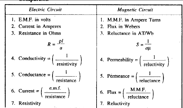
fig 13
Endured emf = -$\ N\ \frac{d\varnothing}{\ \ dt}$
$$\propto \ - \ \frac{d\varnothing}{\ \ dt}$$
Negative sign in faraday law is due to lenz law. {\displaystyle {\mathcal {E}}=-{\frac {\partial \Phi _{\mathbf {B} }}{\partial t}},}
Self-inductance:
A coil is said to have an inductance of 1 Henry if an emf of 1 volts is induced in it when the current flowing through it changes at the rate of 1 Ampere/second.
Energy stored in magnetic field
Force on current carrying conductor placed in a magnetic field
Fig 15(a) Fleming’s Left-Hand Rule (b)
consider a current carrying conductor pleased in magnetic field B, F is Force experiences by conductor , I is current in conductor
θ is angle that conductor makes with the magnetic field.
Force will be maximum when the conductor is perpendicular to the magnetic field. Force will be zero when it is parallel to the magnetic field.
Fig 16
D.C machine
Field winding-are generally made up of copper and are wounded in the region of pole core and named as field coil.
Armature core-it includes number of slots within its edge. The armature conductors are placed in this slots. It provides low reluctance path towards the flux generated with field winding.
Fig 17
Brushes
2-Armature (Rotating part of machine )
3-Commutator and brush gear
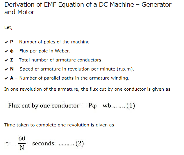
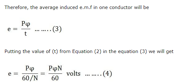
the equation of electromotive force of a generator.
electromagnetic induction the emf equation of D.C machine is given by,
P=total number of poles
A=number of parallel paths through the armature between brushes of opposite polarity
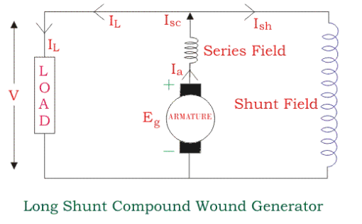
Fig 18 Series generator
Shunt generator-In this type of generator both the field winding and armature winding are connected in parallel with each other.
Fig-19
DC MOTOR
CONSTRUCTION: The D.C motor comprises of following main parts;
Armature core-it includes number of slots within its edge. The armature conductors are placed in this slots. it provides low reluctance path towards the flux generated with field winding.
Armature winding-it can be formed by interconnecting the armature conductor.
The equation of Back emf of a motor
Back emf equation of D.C machine is given by,
P=total number of poles
A=number of parallel paths through the armature between brushes of opposite polarity
The armature reaction causes sparking at the brushes due to delay in commutation inter poles are placed in between the main poles in order to neutralize the effect of armature reaction in brush region and minimize
sparking at the brushes. Theseinter poles has to generate the voltage necessary to neutralize the EMF of self induction in the armature coils undergoing commutation. Theinter poles serves the purpose of counter balancing the armature reaction due to flow of current in armature winding.
Dynamometer wattmeter type watt meter use for measuring the power. in this meter two coils are connected such that, current proportional to the load voltage,(potential coil ) and current proportional to the load current,(Current coil) . .as show in fig 23
Consider ,V=supply voltage, i=load current and , R=resistance of the moving coil circuit, Current through fixed coils, i(f)=I, Current through the moving coil, i(m)=v/R, Deflecting torque will be
Watt meter can measure 5V to 750 V without employing potential transformers (PTs).
Dynamometer watt meters are two type.
A circuit which is excited by single phase ac supply is called single phase ac circuit it can be categories in three category 1- resistive load 2- Inductive load 3- Capacitive load
Resistive Load :
I=im sin(ωt)
im$= \frac{Vm}{R}$
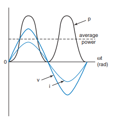
Fig. 26
V= L Im ω Cos (ωt)=L Im ω Sin(ωt+90)
Fig 28 shows Current , Voltage and power of inductor ,
Fig-29
Inductive impedance( XL=2πfL)
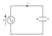
Fig-31(a)
ROOT MEAN SQUARE (RMS) VALUE: The value of an AC voltage is continually changing from zero up to the positive peak, through zero to the negative peak and back to zero again.
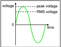
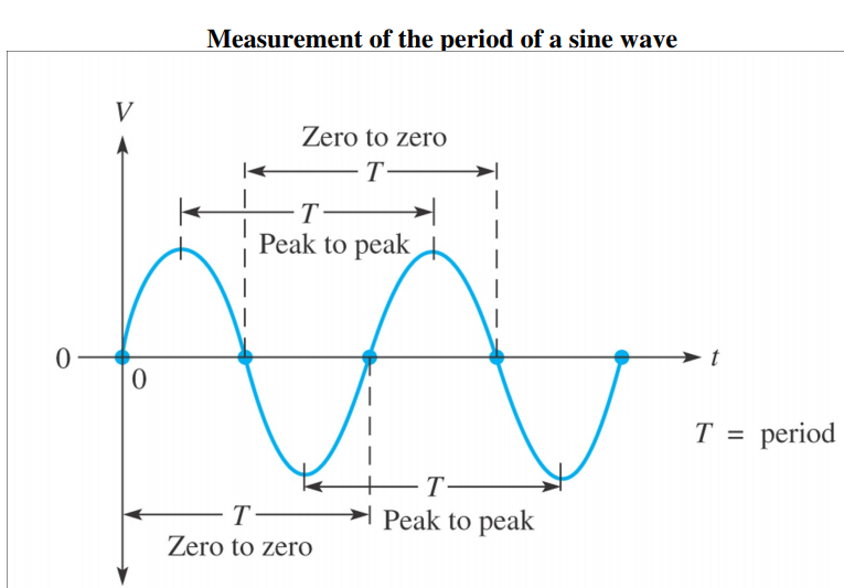
Fig 35
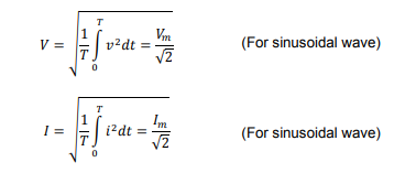
RMS value( root mean square value). If time pride of sine wave (Voltage / current ) is T then RMS value Average value can be written as
Power Factor =Cosθ
Its define as the ratio of real power absorbed by load to the apparent power flowing in circuit its dimension less quantity.
Apparent Power = Active Power + j Reactive Power
Module-4
Fig 39