
The dotted lines the diagram represent true stress and strain
Simple Stresses and Strains
There are following types of stresses are as follows:
Normal Stress: When a force acting in a perpendicular direction to the cut surface of the body, stress is induced and that stress is called normal stress. It can be of two types based on the direction of the force application such as Tensile stress and compressive stress. In tensile stress, force (P) acts away from the body leading to elongation of the body. Whereas, in compressive stress force (P) acts towards the body leading to shrinking of the body.
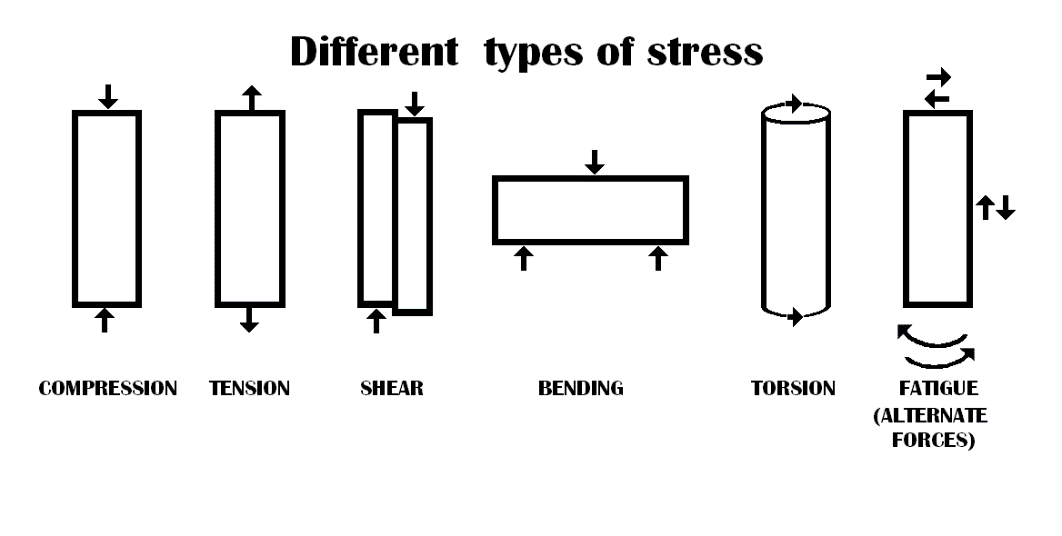
Figure 1 Different type of stress
Types of Strains:
Tensile Strain: The ratio of increase of length to the original length of the body due to external force leading to increase in length of a body is known as tensile strain.
Elasticity: Ability of material to return to its original shape and size after removal of external load is called elasticity.
Elastic limit: The body regain its original shape and size, when an external force applied to the body is within a certain limit is called elastic limit of the material.
Mathematically, it is expressed as follows,
$$E = \ \frac{Stress}{Strain} = \ \frac{\sigma}{\varepsilon}$$
Factor of Safety: The ratio of ultimate tensile stress to its working stress is known as factor of safety. Mathematically, it is expressed as
$$Factor\ of\ Safety\ (FOS) = \ \frac{Ultimate\ Stress}{Permissible\ Stress}$$
Strain can be calculated as follows,
$$\varepsilon = \ \frac{\mathrm{\Delta}L}{L} = \frac{0.22}{300} = 7.333\ \times \ 10^{- 4}$$
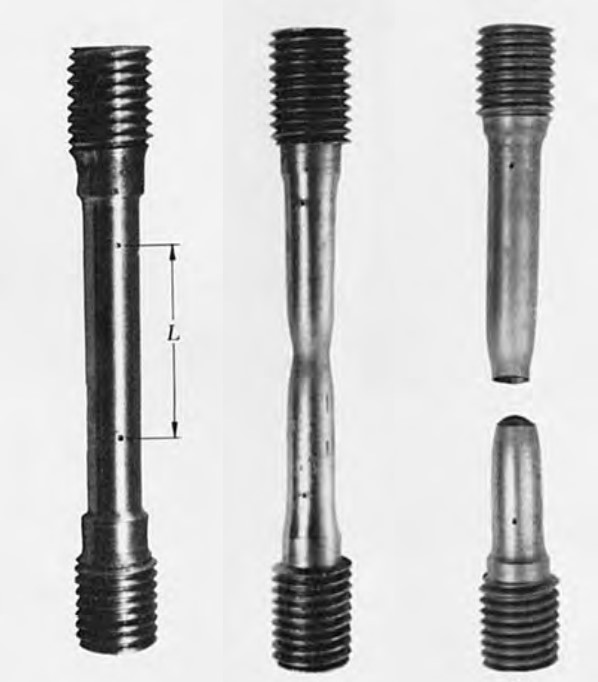
Figure 4 Tensile test of specimen
Ultimate strength: It is defined as the ratio of the maximum load to the original cross-section area.
Rupture Strength: It is defined as the ratio of the rupture load to the original cross-sectional area.
Where, PEL = Load at elastic limit; δEL = Elongation at elastic limit;
$$Modulus\ of\ Resilience = \ \frac{Proof\ Resilience}{Volume}\ = \ \ \frac{\sigma_{EL}^{2}}{2E}$$
Where,
$$\sigma = \frac{P}{A}$$
Principle of Superposition:
Structural member is subjected to a number of forces acting at the end and in-between point along its length as well. With application of principle of superposition, these members can be analysed by breaking into smaller portion and adding up later to get the resultant. Resulting strain will be equal to total sum of strains caused by individual member and is shown in the Figure 6.
Where, Pn = Force acting on section, n
Ln = Length of section, n
$$\mathrm{\Delta}L = \ \sum_{}^{}\frac{PL}{AE}\ = \ \frac{1}{E}\ \left\lbrack \frac{P_{1}L_{1}}{A_{1}} + \ \frac{P_{2}L_{2}}{A_{2}} + \ ..\ .\ ..\ + \ \frac{P_{n}L_{n}}{A_{n}} \right\rbrack$$
Where, An = Cross-section area at section, n;
$$\mathrm{\Delta}L = \ \sum_{}^{}\frac{PL}{AE}\ = \ \ \left\lbrack \frac{P_{1}L_{1}}{A_{1}E_{1}} + \ \frac{P_{2}L_{2}}{A_{2}E_{2}} + \ ..\ .\ ..\ + \ \frac{P_{n}L_{n}}{A_{n}E_{n}} \right\rbrack$$
Where, E1, E2, and En = Different young’s modulus for different sections.
$$\mathrm{\Delta}L = \ \frac{4\ P\ L}{\pi\ E\ d_{1}d_{2}}$$
Where, d1 = diameter at smaller end; d2 = diameter at bigger end;
$$\mathrm{\Delta}L = \ \frac{P\ L}{\left( b_{2} - \ b_{1} \right)\ t\ E\ }\log_{e}\frac{b_{2}}{b_{1}}$$
Where, b1 = Width at smaller end; b2 = Width at bigger end; t = thickness of the bar;
Cross-section area for different section can be calculated as follows,
$A_{1} = \ \frac{\pi}{4}\ (30)^{2} = 706.86\ {mm}^{2}$;
The F.B.D of three section for the load distribution is shown in the Fig. (ii).
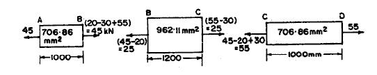
$$\mathrm{\Delta}L_{3} = \ \frac{P_{3}L_{3}}{A_{3}\ E} = \ \frac{55\ \times 1000\ \times 1000}{706.86\ \times 205\ \times 100\ } = 0.380\ mm$$
Total deflection of bar can be calculated as follows,
Let λ be the specific weight of the materials = ρg and it is expressed in kN/m3
Deformation can be calculated as follows,
Mathematically,
$$\nu = \ \frac{Lateral\ Strain}{Longitudinal\ Strain} = constant = \frac{1}{m}$$
$$\frac{\delta V}{V} = \ \varepsilon_{1} + \ \varepsilon_{2} + \ \varepsilon_{3}$$
$$\varepsilon_{v} = \frac{\delta V}{V} = \ \varepsilon_{1} + \ \varepsilon_{2} + \ \varepsilon_{3} = \left( 1 - \frac{2}{m} \right)\ \left( \frac{\sigma_{1} + \ \sigma_{2} + \sigma_{3}}{E} \right)$$
Volumetric Strain, $\varepsilon_{v} = \frac{\delta V}{V} = \ \varepsilon_{1} + \ \varepsilon_{2} + \ \varepsilon_{3} = (\ 8.333 - 2 \times 2.5) \times 10^{- 4} = 3.333 \times 10^{- 4}$
Volume, V = 300 x 30 x 30 = 270000 mm3 = 27 x 104 mm3
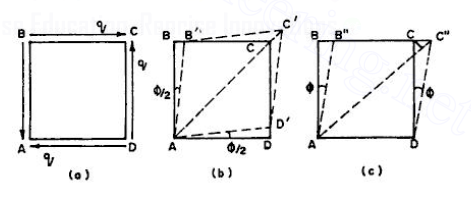
Figure 12 Linear Strain due to Shear
$$G = \ \frac{m\ E}{2\ (m + 1\ )}$$
Bulk Modulus: It is defined as the ratio of direct stress to the corresponding volumetric strain. It is denoted by K.
Figure 13 Linear Strain due to 3 mutually perpendicular stress
Volumetric strain of cube is given as follows,
Equating the two equations, we get
$$\frac{\sigma}{K} = \ \frac{3\sigma}{E}\left( 1 - \frac{2}{m} \right)$$
Solving this equation for ‘m’, we get
$$\frac{1}{m} = \ \frac{3K - 2G}{6K + 2G}$$
Area of bar is calculated as,
$$A = \frac{\pi}{4}\ (25)^{2} = 490.87\ {mm}^{2}$$
$$\frac{81.49}{E} = \ 4.25 \times 10^{- 4}$$
$$\mathbf{E = 1.917\ \times \ }\mathbf{10}^{\mathbf{5}}\mathbf{\ \ }\frac{\mathbf{N}}{\mathbf{mm}^{\mathbf{2}}}$$
From the relation between E & G,
$$G = \ \frac{m\ E}{2\ (m + 1\ )}$$
$$K = \frac{3.542\ \times 1.917\ \times \ 10^{5}}{3\ (3.542 - 2)} = \mathbf{1.468\ \times \ }\mathbf{10}^{\mathbf{5}}\mathbf{\ }\frac{\mathbf{N}}{\mathbf{mm}^{\mathbf{2}}}$$