
The expected resonant frequency the system can calculated frac
OBJECTIVE
THEORY
$$K = \frac{1}{2}LI^{2}$$
This energy cycles back and forth between forms, creating an oscillatory pattern, given that the system is isolated and does not lose any energy.
The solution being: I(t) = Imaxsin (ωt+φ)
In addition, the expected resonant frequency of the system can be calculated as:
RESULTS
| Inductors | L / mH | R / Ω |
|---|---|---|
| Coil | 22.5 | 7.5 |
| Solenoid | 7.62 | 1.7 |
| Cgreen, Lcoil | ω / radians/s | ω’ / radians/s | f / 1/s | f’ / 1/s |
|---|---|---|---|---|
| Experimental | 685 | 664.415 | 109.021 | 105.745 |
| Theoretical | 689.819 | 669.382 | 109.788 | 106.536 |
| % Difference | 0.7 % | 0.7 % | 0.7 % | 0.7% |
| Cblue, Lcoil | ω / radians/s | ω’ / radians/s | f / 1/s | f’ / 1/s |
|---|---|---|---|---|
| Experimental | 997 | 982.971 | 158.677 | 156.445 |
| Theoretical | 971.400 | 956.996 | 154.603 | 152.311 |
| % Difference | 2.6 % | 2.7 % | 2.6 % | 2.7 % |
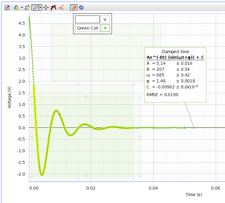
Figure 1 - Green Capacitor and Coil
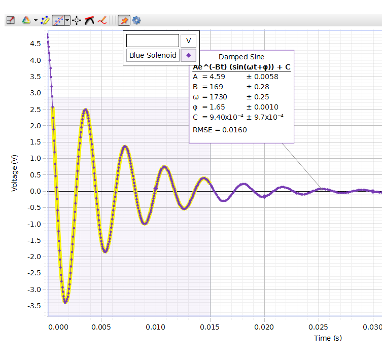
Figure 4 - Blue Capacitor and Solenoid
DISCUSSION QUESTIONS
What makes the sine wave amplitude decreasing so fast that you have a few oscillations only?
We only obtained a few oscillations due to damping caused by the resistor. The damping constant, B=R/2L, is very large in this experiment, meaning that the amplitude of the wave will decrease very rapidly, as evidenced in the results.