The radius and angle dont change with time
One has to push the loop against a repulsive force.
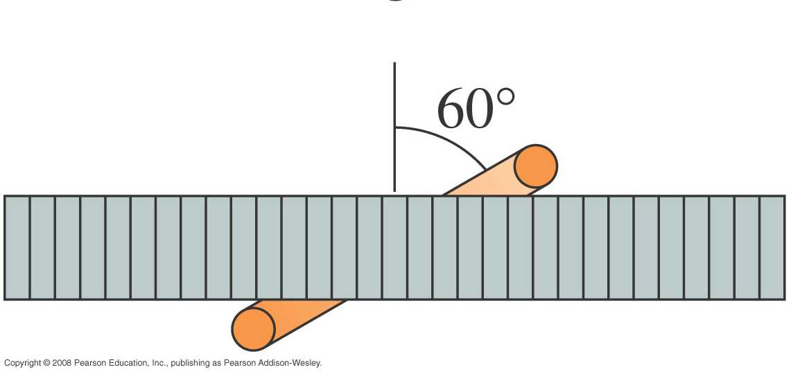
As the loop enters the region between the poles the magnetic flux linked with the loop increases. Therefore the motion of the loop in the magnetic field induces a current in the loop in the direction shown. This induced current tends to oppose the flux increase by creating a magnetic field opposite in direction to that which existed due to the magnetic poles. In other words the induced current is such that the force the loop experiences due to this current opposes the loop to enter the region between the poles(Lenze's law) . The magnetic poles of the induced current loop are also shown in the diagram . The net magnetic force on the loops is to the right.
| 34.4 |
|
4 | |
|---|---|---|---|
| Order: |
b. No current. A changing magnetic flux induces a current but here it is constant.
c. Counterclockwise. Since the 'dot' field is decreasing hence the induced magnetic field is'dot',i.e. Out of the page and by the right-hand rule the induced current is counter clockwise.
d. Counterclockwise. The decreasing current in the lower loop causes the flux through the upper loop to decrease, inducing an
| upward | magnetic | field. |
|---|
34.7
b. Yes, up. The induced downward field is like a magnet with its north pole on the bottom, which is repulsed by the bar magnet.
c. Yes, down. By Newton’s third law, the bar magnet experiences an equal and opposite force and hence is pushed down.
c. Right to left. Flux through the loop decreases as the magnet is withdrawn. There fore to prevent this change(Lenze's Law) the induced current flows in such direction that a north pole is induced at the left side of the coil and it attracts the south pole of the retreating bar magnet. Hence the current as seen from the retreating bar magnet side is counterclockwise. Therefore this time the induced current flows from right to left in the current meter.
Exercise and problems
| Which gives us, | v | = | E | = | = |
|
|||
|---|---|---|---|---|---|---|---|---|---|
|
|||||||||
| lB | ( 1.0 m | ) | |||||||

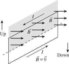
Since a motional emf was developed the field must be perpendicular to vr. The positive charges experienced a magnetic force to
Solve: This is a straightforward use of Equation 34.3
| B | = | E | = | 0.050 V | = | |||||
|---|---|---|---|---|---|---|---|---|---|---|
| vl | ( | 5.0 m/s | )( | 0.10 m | ) | |||||
When the loop is tilted it still encloses the solenoid . Now initially the area of the loop was perpendicular to the field but now it is tilted hence we can use the formula
According to Lenz’s law, the induced current creates an induced field that opposes the change in flux.
Solve: The original field is into the page within the loop and is changing strength. The induced, counterclockwise current produces a field out of the page within the loop that is opposing the change. This implies that the original field must be increasing in strength so the flux into the loop is increasing.
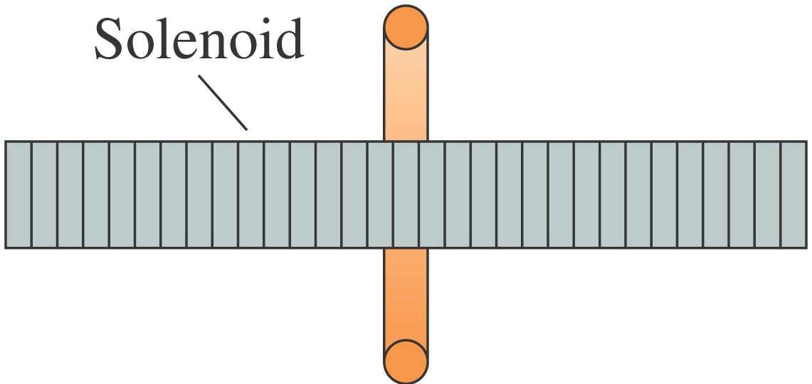
Solve: The current shown produces a field to the right inside the solenoid(using right hand rule). So there is flux to the right through the surrounding loop. As the current in the solenoid increases there is more field and more flux to the right through the loop. There is an induced current in the loop that will oppose the change by creating an induced field and flux to the left. This requires a counterclockwise current when seen from the left end of the solenoid.
34.11. Model: Assume the field is uniform.
| I | = E= / . |
|
to | |||||||||||||||||||||||
|---|---|---|---|---|---|---|---|---|---|---|---|---|---|---|---|---|---|---|---|---|---|---|---|---|---|---|
| E | = | A |
|
= | π r | 2 | = | π ( | 0.050 m | ) ( | 0.50 T/s | ) | = | 3.9 10 V−3 | = |
|
||||||||||
| I | = | E | = | 3.93 10 V− | = | = | ||||||||||||||||||||
| R | ||||||||||||||||||||||||||
the induced field needs to point into the page. Thus the induced current must flow clockwise.
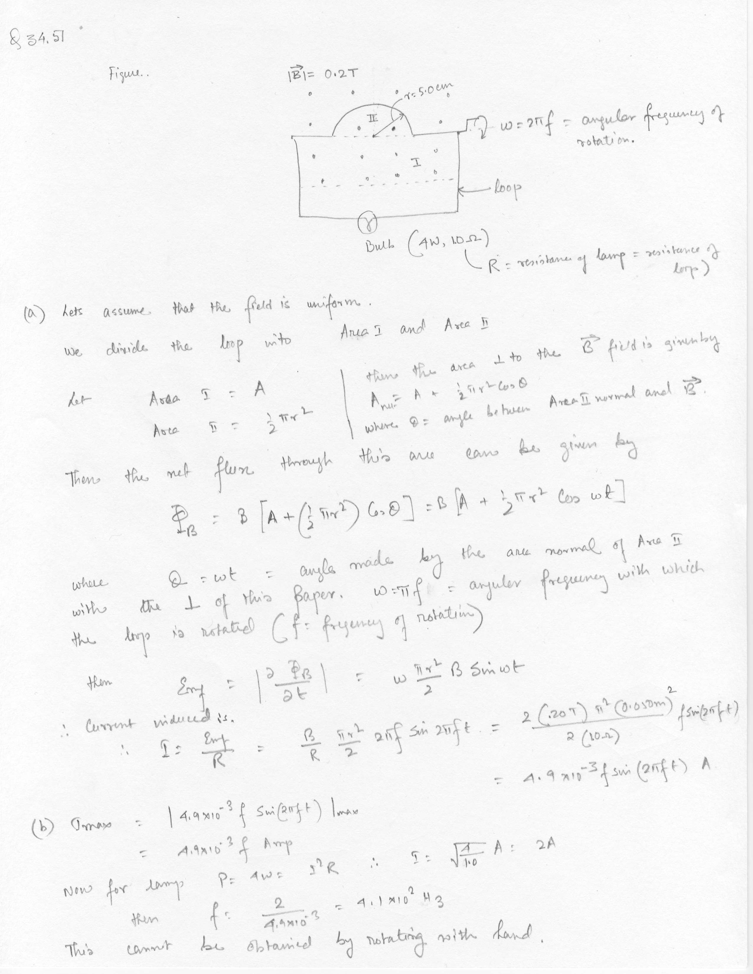
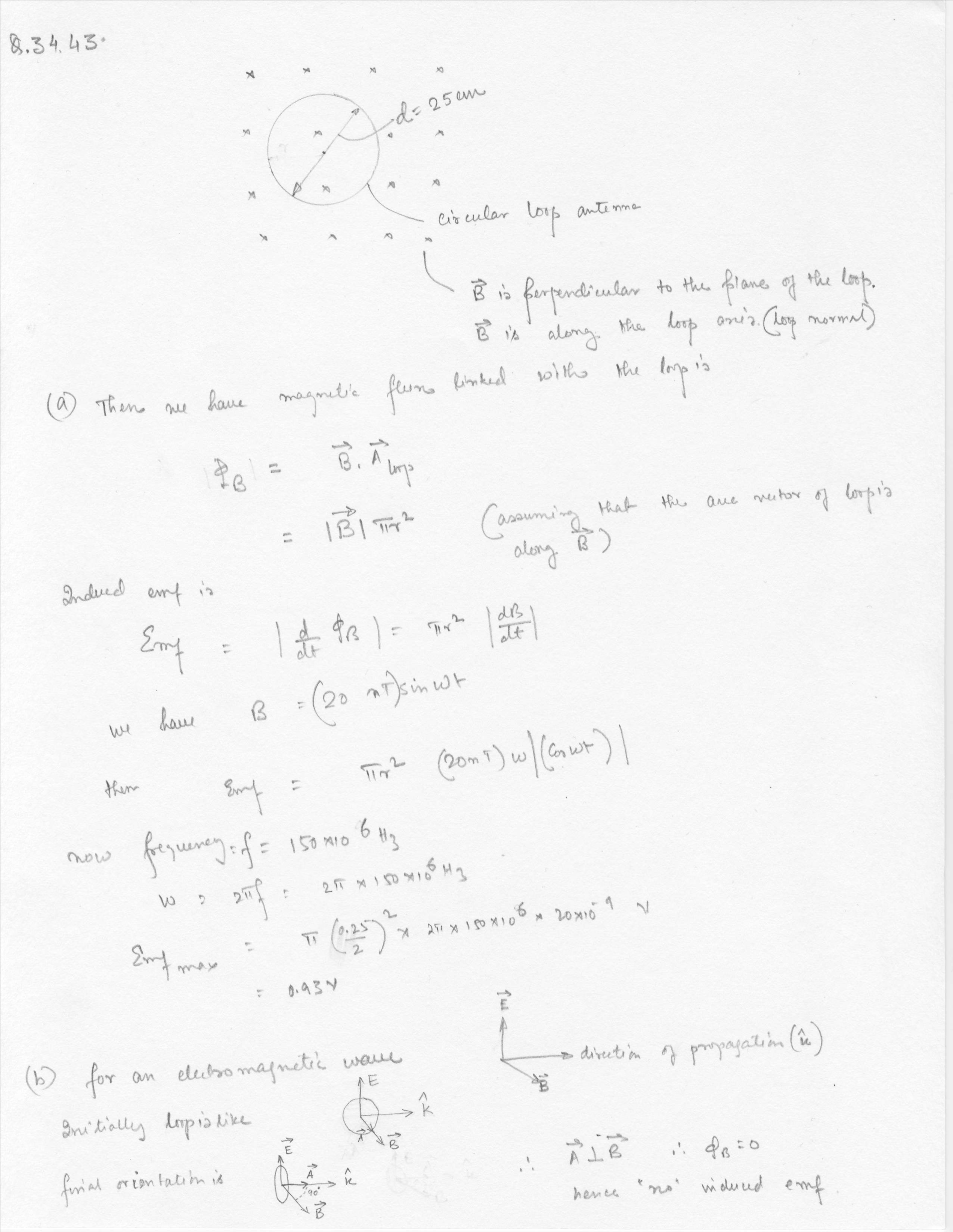
(c)The diagram illustrating the expression of magnetic flux is as follows
| r Now A | and so | r r A B | = | 0 | Wb. That is, the field does not penetrate the plane of the loop. If Φ= |
|---|
34.27.
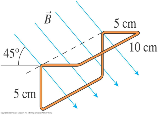
The magnetic strength is changing so the flux is changing and this will create an induced emf. The magnetic field is at an angle θ = 60° to the normal of the plane of the coils.
Solve: The flux for a single loop of the coil is . Or The radius and angle don’t change with time, but B does.
Visualize:
| I | = | E loop | = | ||
|---|---|---|---|---|---|
| loop | R |
|
The flux through a rectangular loop due to a wire was found in Example 34.5. The total flux is
34.40. Model: Since the solenoid is fairly long compared to its diameter and the coil is located near the center, assume the solenoid field is uniform inside and zero outside.
Visualize:
| I | = | E coil | = | 1 | N | = | N | coil π r coil 2 | d | | µ 0 | NI | | = | N | coil π r coil 2 µ 0 | |||||||
|---|---|---|---|---|---|---|---|---|---|---|---|---|---|---|---|---|---|---|---|---|---|---|---|
| coil | R | R | coil | R | dt | | l | |
Rl | ||||||||||||||
| We used the fact that the coil flux is confined to the area | |||||||||||||||||||||||
| A coil | = | π r coil 2 | of the coil, not the larger area of the solenoid. The current is | ||||||||||||||||||||
changing uniformly over the interval 0 s ≤t≤ 0.02 s at the rate |dI/dt| = 50 A/s so the induced current during this interval is
34.41.
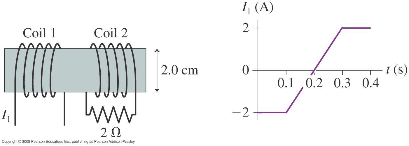
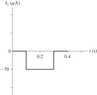
| Solve: (a) From 0 s to 0.1 s and 0.3 s to 0.4 s the current in coil 1 is constant so the current in coil 2 is zero. Thus | |||
|---|---|---|---|
| I | (0.05 s) | = | |
| 34.43. |
|
|---|---|
| E | = | = | A |
|
= | π r | 2 | = π r | 2 ω B 0 |
|---|
The cosine will oscillate between +1 and −1 so the maximum emf is
Alternate solution
| V 2 | = | N | 2 | V | ⇒ | N 1 | = | V 1 | N | = |
|
= | 12,500 |
|
|||||||||||||||
|---|---|---|---|---|---|---|---|---|---|---|---|---|---|---|---|---|---|---|---|---|---|---|---|---|---|---|---|---|---|
| N 1 | 1 | V 2 | 2 | ||||||||||||||||||||||||||
| = ∆I V | |||||||||||||||||||||||||||||
| (b) The input power equals the output power and we recall that P | |||||||||||||||||||||||||||||
| P | = | P in | ⇒ | I 1∆V 1 | = | I | ∆V 2 | ⇒ | I 1 | = | I | 2 | ∆V 2 | = | ( | 250 A 120 V ) | = | ||||||||||||
| out | 2 | ||||||||||||||||||||||||||||
Assess: These values seem reasonable, because houses have low voltage and high current while transmission lines have high voltage and low current.
34.51. Model: Assume that the magnetic field is uniform in the region of the loop.
| P | = | I R | ⇒ | I | = | P R | = |
|
Ω = |
|
|---|
Alternate Solution