This covers quality and size the coarse and fine aggregates

Structures for Medium Rise Construction Short Course Participant Guide© Housing Industry Association Ltd
It is a requirement that participants undertaking the short course ‘Structures for Medium Rise Construction’ have successfully completed the following unit.
|
|---|
|
|---|
WELCOME ..................................................................................................................................... 7
WHAT THE COURSE COVERS .......................................................................................................... 7
USING THIS GUIDE ........................................................................................................................ 9
INTRODUCTION .......................................................................................................................... 10
1.1. INTRODUCTION ................................................................................................................. 12
1.2. STATICS AND FAILURE ....................................................................................................... 14
3.1. MASS,FORCE,PRESSURE,STRESS AND CONSISTENT UNITS ............................................... 20
3.2. DESCRIBING PRIMARY LOADS ............................................................................................ 22
3.6. UNIFORMLY VARYING LOAD ............................................................................................... 35
3.7. APPLIED AND DESIGN FORCES ........................................................................................... 35
4.3. SHRINKAGE EFFECTS ........................................................................................................ 40
4.4. THERMAL EFFECTS ........................................................................................................... 40
CLASS ACTIVITY 6–DESIGNING FOR MATERIALS ........................................................................... 43
6.0 STRUCTURAL PRINCIPLES - STRUCTURES UNDER LOAD ......................................... 44
CLASS ACTIVITY 7–STRUCTURES UNDER LOAD............................................................................ 45
6.2. BEAM THEORY, REACTIONS AND MOMENTS ......................................................................... 46
6.7. SHEAR WALL .................................................................................................................... 56
CLASS ACTIVITY 8–STRUCTURES UNDER LOAD............................................................................ 57
8.2. BENDING MOMENTS,SHEAR FORCES AND DEFLECTION ...................................................... 62
CLASS ACTIVITY 9–STRUCTURES IN BENDING .............................................................................. 64
9.2. COLUMNS AND BUCKLING .................................................................................................. 76
9.3. SLENDERNESS AND END FIXITY .......................................................................................... 78
10.0 STRUCTURAL PRINCIPLES - COMMON MATERIALS ................................................... 86
10.1. SOIL ............................................................................................................................. 86
10.6. ALUMINIUM ................................................................................................................... 99
11.0 DEMOLITION ................................................................................................................... 100
12.0 FOUNDING MATERIALS AND FOUNDATIONS ............................................................. 111
12.1. INTRODUCTION ........................................................................................................... 111
|
|---|
CLASS ACTIVITY 16–TEMPORARY WORKS ITEMS ...................................................................... 136
14.2. FORMWORK AND FALSE WORK .................................................................................... 137
15.0 SITE SET-OUT ................................................................................................................ 163
15.1. INTRODUCTION ........................................................................................................... 163
16.3. MASS CONCRETE ........................................................................................................ 167
16.4. REINFORCED CONCRETE – STRIP FOOTINGS ................................................................. 169
18.1. STRUCTURAL PROPERTIES .......................................................................................... 180
18.2. OFF-FORM BUILDING ELEMENTS .................................................................................. 181
19.1. REINFORCED CONCRETE ............................................................................................. 185
CLASS ACTIVITY 22–STRUCTURAL SLAB ON GROUND ................................................................. 193
21.0 TRANSFER BEAMS ........................................................................................................ 198
21.1. STRUCTURAL STEEL .................................................................................................... 198
CLASS ACTIVITY 25–SUSPENDED STRUCTURAL SLAB ................................................................. 207
23.0 TILT PANELS .................................................................................................................. 208
24.0 OTHER STRUCTURES ................................................................................................... 216
24.1. BLOCK WORK ............................................................................................................. 216 CLASS ACTIVITY 28–BLOCKWORK ............................................................................................ 218 24.2. ROOF STRUCTURES .................................................................................................... 219 CLASS ACTIVITY 29–ROOF SYSTEMS ........................................................................................ 224 24.3. COMPOSITE BEAM ....................................................................................................... 225 CLASS ACTIVITY 30–COMPOSITE SYSTEMS ............................................................................... 227 24.4. INSTALLATION OF SERVICES INTO THE STRUCTURE ....................................................... 228 CLASS ACTIVITY 31–SERVICES REQUIRED FOR THE STUDENT ACCOMMODATION PROJECT .......... 229 CLASS ACTIVITY 32–SEWER SERVICE ....................................................................................... 238 CLASS ACTIVITY 33–STORMWATER .......................................................................................... 245 CLASS ACTIVITY 34–ELECTRICAL SERVICES .............................................................................. 247 CLASS ACTIVITY 35–VENTILATION ............................................................................................ 253 CLASS ACTIVITY 36–AIR-CONDITIONING .................................................................................... 254
Thank you for choosing to study with the Housing Industry Association, Australia’s premier Residential Building Industry Association.
You are enrolled in the HIA Structures for Medium Rise
Construction Short Course which forms part of our CPC50210 Diploma of Building and Construction (Building) Program. You may be undertaking this as a standalone course or as part of a diploma qualification.
This course is designed and assessed to meet the requirements of the following unit(s) of competency:
|
|---|

If you are already working, you will know how hard it is to find time for yourself and your family. To make your study a
success you need to make firm time commitments to all three areas of your life: work, family, and study
|
|---|

|
|
|---|


|
|---|
This course supports builders, project managers and related construction industry professionals responsible for ensuring the structural integrity of materials as well as building and construction work so that site safety and quality control measures are maintained during medium rise and commercial projects.
The course is based on a fictitious Building and Construction Project. The project is a three storey student accommodation building.
As this Short Course leads to a nationally recognised Unit of Competency, we need to assess your skills and knowledge once you complete the course.
Industry and training experts have designed the assessment tasks that are industry relevant, practical and achievable. The tasks are also designed to meet the standards set by industry through the Approved Training Package CPC08 Construction, Plumbing and Services Integrated Framework.

If additional time is required for submission, this may be negotiated by contacting the training coordinator no less than 3 days before the final submission date.
|
|---|
Where re-submissions have been requested, the final date for completion of the unit or cluster of units will be extended. The extra time allowed will be negotiated between the participant and trainer/assessor.
A maximum of two re-submissions will be allowed before the participant will be required to attend further training. Any further training required may incur additional costs to the participant.
| AT1 | ||
|---|---|---|
| AT2 |
|
|
| 1.0 |
|
|
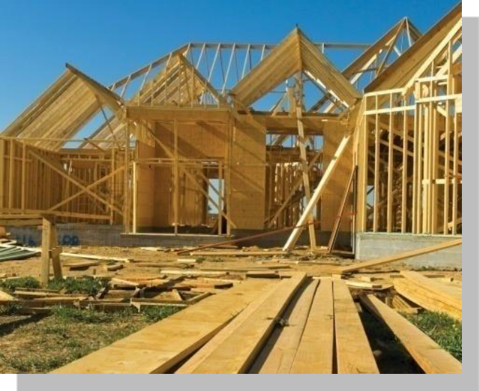
The structure of a building is the part which is responsible for maintaining the shape and integrity
of the building under the influence of the forces to which it is likely to be subject.
|
|
|---|
• Class 1B - Which is not located above or below another dwelling or another
Class of building other than a private garage.
o Class 4 - A dwelling in a building that is Class 5, 6, 7, 8 or 9 if it is the only dwelling in
the building.
o Class 7 - A building which is a car park or for storage, or display of goods or produce
for sale by wholesale.
assembling, altering, repairing, packing, finishing, or cleaning of goods or produce is
carried on for trade, sale or gain.
• Class 9C - An aged care building.
o Class 10 - A non-habitable building or structure.
that are to be assumed while designing and building a structure. This series of standards is
commonly known as the 'loading codes'.
Engineering. Even the most complex of structures shares many of the basic concepts and issues
in common with simple structures. Structural engineering is primarily the study of:
|
|---|
Materials


Forces are also referred to as loads or actions. Often we can measure or predict them quite accurately (e.g. the weight of a volume of concrete) and sometimes we can’t or it’s difficult and costly to do so with useful certainty (e.g. from wind or earthquakes). All applied forces on and in a building have to be balanced by an equal value and opposite direction force somewhere (e.g. the soil reactions under the footings; supports under a beam).
Engineers call this “equilibrium” and use the term “statics” to describe this process of working out and balancing all the forces. (“Static” means stationary, so if all the forces balance nothing starts moving!).
|
|---|

Obviously fire is not a planned event but it is foreseeable so we have to ask and account for what might happen with the priority always on preservation of life, then upon containment from spreading to further structure.
Fire Resistance Level (FRL) of a material or building system (as defined in the Building Code of Australia (BCA/NCC)) is the grading period in minutes for three criteria: structural adequacy, integrity and insulation.
Materials we commonly use and engineer in structures include soil, concrete, steel, timber, masonry, and glazing. Even materials we might consider to be “non-structural” (e.g. plasterboard, corrugated roof sheeting) must behave structurally just to be used and stay in place.
When we start looking at real structures the main expected effects, where we have to consider the interaction of forces and materials, are:
| o | STABILITY |
|---|
|
||
|---|---|---|
 |
||


|
|
| o |
|
| o | |
| o | |
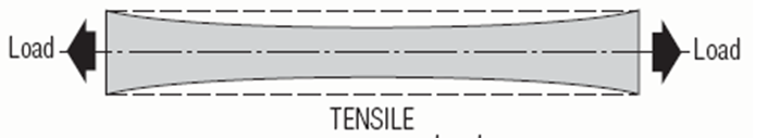
Tensile stress: Tension occurs when forces tend to cause the material to stretch or crack.
Shear stress: Shear occurs where forces tend to cause adjacent sections to slide across each other.

Working individually, give some examples in a medium rise building structure where structural elements are subject to:
|
|---|
decimal system of weights and measurements derived from (and extending) the metric system of
units.
Time second (s)
Electric current Ampere (A)
Derived units are just what they sound like – they are ‘derived’ through a process of calculation.
Some are included in the table below:
|
|---|
Although the terms are often used interchangeably force and mass are not the same thing.
Common conversions (under Earth’s gravity) are:
1kg → 10N
100kg → 1kN
1t → 10kN1 tonne (t) is technically a megagram (a million grams and a thousand kilograms) but the term is never used.
To manage what forces do to materials we need to understand how concentrated, or intense they are, which creates reactive stress in the material.
The basic SI unit for stress is the Pascal (Pa) which is defined as the spreading out a force of 1N (e.g. from 100g mass under gravity) over an area of 1m2. This unit (1Pa = 1N/m2) is too small for any practical use in the building industry, where we commonly need to refer to kPa (kilopascal) and MPa (megapascal). We also use the same units for pressure which is an applied stress to a structure (e.g. wind pressure on a roof, water pressure on a basement wall).
When a building component or material is subjected to loading it is said to be subjected to a stress, and because of that stress it must change shape – even if microscopically. The nature of that stress is determined by the manner in which the loading occurs.
As well as considering the different types of loading we have to consider how the loads are applied. There are three common types of applied loads we design for:
|
|---|
By calculating the volume of each member and multiplying by the unit weight of the materials from which it is composed, an accurate dead load can be determined for each component.
Dead load = volume of member x unit weight of materials
= 2400
100
= 24 kN/m³
The unit weight of materials commonly used in building and construction are contained in the BCA referenced standard AS/NZS 1170.1 and the supplement to AS/NZS 1170.1.
The table below gives the unit weight for some common construction materials.
|
|
|
|
|
|
|
|


12.5m
|
|---|

|
|---|
Area of floor = 6.0 m x 4.0 m = 24 m2
Live load rating of a house = 1.5 kPa
Therefore, live load of floor
= 24 m2 x 1.5 kPa
= 36 kNLive load ratings for the various building types are also contained in the BCA referenced standard
Table 2: Live load comparisons
|
|||
|---|---|---|---|
|
|---|
Wind blowing against building results in positive pressure which pushes against the building. Wind acting on the leeward side of the building results in negative pressure which pulls at the building whilst at edges such as at gable ends eaves and ridges a vortex region (a swirling movement of air) is created.
Just as we see for stress calculations that Stress = Force / Area, if we rearrange this simple equation (and remember that Pressure is just an applied stress) it is still true that:
So, if we multiply the wind Pressure (in kPa) by the surface area it acts on (in m2) we will work out the applied wind Force (in kN). Remember, we must design with Forces!
|
|---|
The diagram below gives an indication of the range of wind loads that may be experienced by a structure. There is significant variation in these depending on the type of structure and its location. Note especially that wind blowing horizontally produces vertical forces on the roof. For a steeper pitched roof (as below) the windward side may be vertical downwards force but for the more common flatter roof pitches the whole roof is subjected to vertical upwards force.
Wind pressure
When wind flows around a building, it can produce some very high suction pressures. These occur mainly at the leading edges. In these areas, the cladding has to be firmly fixed to the structure and the roof has to be firmly held down. The flatter the roof, the higher the suction forces are on the roof and the more important it is to make sure that the tie-down mechanisms are fixed securely into the structure.
|
|---|

|
|---|
Concrete shrinks over time for 2 reasons. A small amount of shrinkage occurs as the water in the mix reacts with the cement to develop strength-gain and takes up less volume after this reaction. This needs to happen and MUST be allowed to. The other and potentially larger source of shrinkage is from allowing water to evaporate from the poured concrete due to inadequate curing, which then hinders the chemistry of strength gain. This MUST be minimized since it also produces weaker concrete which is less able to resist damaging shrinkage effects.
|
|---|
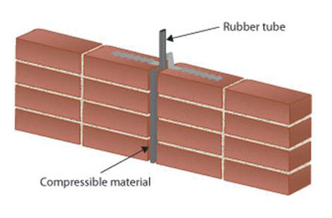
Expansion joints are provided at these points so that the structure is physically separated and can expand without causing structural damage.
|
|---|
Another structure-based solution might be to increase the stiffness of the structure itself at the design stage (e.g. by deepening slabs or beams). This helps the structure not to vibrate in sympathy with the source but still might allow vibrations to pass through it to other locations.
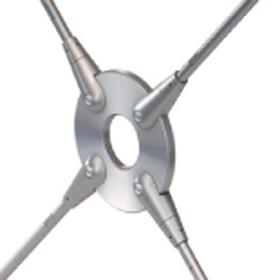
The diagram shows a flue stack on a roof connected by two cables. The wind blows onto one side of the cable. It is possible that wind-driven vibration might originate in the cable and become a problem in the structure via its connection points. This is in addition to the primary wind loading onto the stack itself trying to blow it over.
|
|---|
Point loads are represented by an arrow in the direction the load acts and are expressed in units of kN.
Point load
o The beam’s own weight.
o The weight of the floor/slab it is supporting.

Give reasons for each example
|
|---|
For the same load and location, different materials will perform differently. Why ?
The strength of a structural member is the maximum stress (= force/area) resistance it is able to offer in reaction before fracture (in tension) occurs. This breaking strength is also referred to as 'ultimate tensile strength' – often abbreviated to UTS.
|
|---|
Plasticity is different to elasticity. If a material deforms when loaded and does not return to its original shape when the load is removed, permanent deformation occurs. This is called 'plastic behaviour'. A plastic material will retain some of the shape it becomes under load even when the load is removed (after some minor component of elastic recoil).
Malleability is a form of ductility but in compression, such as when a material can be hammered or otherwise worked into various shapes. Lead is an extremely malleable material but this property rarely is relevant to structural engineering.
|
|---|
Yield is a clearly defined dividing point between the elastic (reversible) and plastic (permanent) parts of the curve. Steel does this in tension and compression. Concrete does it in neither (because it is brittle). Yield is measured in MPa.
|
|---|
Creep is a special property of some materials which occurs for high loads applied over a long period of time. The load may create stresses that are close to the top of the elastic range which if removed quickly because no permanent deformation but if the load is maintained for a longer period of time the material can still distort long-term.
A concrete slab-on-ground usually cannot freely shrink so it would develop tensile stresses and may tend to crack, for which reinforcement is placed to manage this.
|
|---|
|
|---|
|
|---|
The calculations for Strengths Limit State then ensure that the value of the factored Design Loads must not exceed the value of the factored Design Capacity knowing that the expected applied loads are highly likely to be always much less than the expected material strength. Previous design methods achieved much the same result and referred to the concept of a Factor of Safety between the expected allowed maximum stress in materials (e.g. allowed bending stress in steel couldn’t exceed x 0.66 of yield) and the expected applied loads.
|
|---|

CLASS ACTIVITY 6 – DESIGNING FOR MATERIALS
Class Discussion
|
|---|
|
||
|---|---|---|
| 6.0 | ||
The load path is simply the direction in which each load will pass through connected members. The sequence commences at the highest point of the structure working all the way down to the footing system, which transfers the total load of the structure to the foundation.
The key point is that ALL loads in a structure must go somewhere, eventually being resisted by the reactions from the foundations to the footing system. If all the applied forces in a structure are added up they must be equaled by the sum of all the foundation reactions. This is statics.
|
||
|---|---|---|
 |
||

for in the building’s design. If movement occurs that is not allowed for, structural problems may result. Buildings are designed to maintain a state of equilibrium, which is the ability to resist any external loads without moving.
Example: A point load on a beam
Structural members are the primary load bearing components of a building. The structure of a building constitutes about 30% of the construction cost. Good structural design can result in cost efficient building.
|
|---|
Beams are generally horizontal members which transfer loads horizontally along their length to the supports where the loads are usually resolved into vertical forces.
|
|---|
Continuously beams multi-span and are supported by three or more support points (creating 2 or more connected spans). They deflect less than adjacent single-span beams of the same span because the positive and negative bending cancels each other out. Generally a continuous span is 20% more efficient than a simple span as it is able to span longer distances.
|
|---|
|
|
|---|
|
|---|
These always occur simultaneously.
|
|---|


|
|---|

However at a point above the supports the beam is experiencing two forces acting in a opposite vertical directions. In this beam case, the maximum shear is over the supports (where the bending effects are zero) and the maximum bending is at the midspan (where the shear is zero).
|
|---|
o Structural.
o Serviceability.
• material properties,
• end fixing and
Serviceable deflection considers the comfort of the occupants and may be considerably less than that caused by the initial structural loads. Therefore when calculating an upper limit of deflection for serviceability it may be expressed as span/300 or 10 mm whichever is the lesser.
|
|---|

|
|---|
Where the brace needs to act in compression it is called a strut.
|
|---|
Sometimes adding braces is not possible because the internal space needs to be clear but the lateral wind loads still must be resisted. In this case we resort to “portal action” – the word portal means an opening – and this requires fixing the upper pin joints so they rigidly stay as right angles. This is how any portal frame works and it might also have rigid column base-footing joints as well.


|
|---|
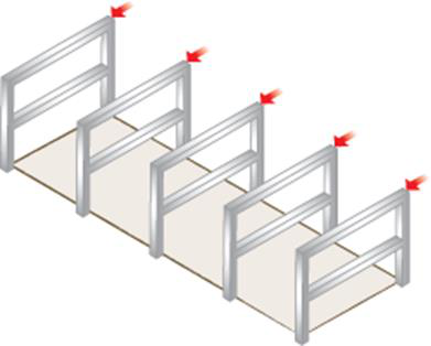
'Bents' are braced or fixed frames which are designed to carry both vertical and lateral loads across the length of a framed structure.
Lateral forces can be more critical across the width of a rectangular building. Usually shear walls or brace frames are used as they are more efficient.
|
|---|

Shear wall: A timber, concrete or masonry wall will resist changes in shape. The wall will therefore transfer lateral loads to the floor or foundation.
Braced frame: The frame is timber or steel and is braced with diagonal members.
|
|---|
|
||
|---|---|---|
 |
||
|
|---|
| 7.0 | ||
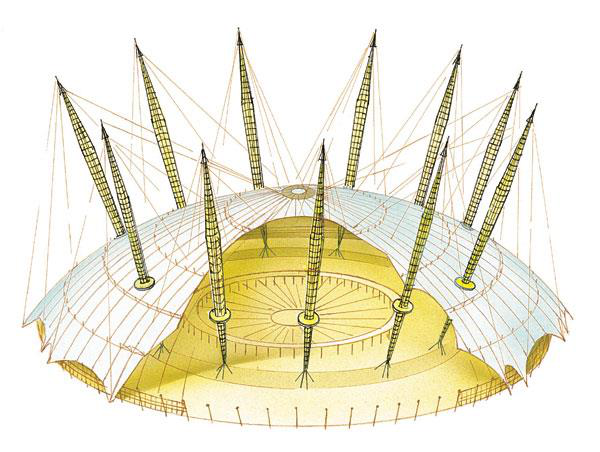
Generally any structural component which acts purely in tension is referred to as a tie. Chiefly we are interested to check that the tensile stress created (= force / area) does not exceed the strength capacity of the material. It is usually essential that ties must never be allowed to go into
compression (if loads change) since they will then be ineffective. Sometimes how much the tie elongates elastically might also be important. Typical tie components include: any cable
structures, bracing, tie-down rods.• loading members only in pure compression or pure tension, meaning the structure will only fail if the cables yield or the rods buckle
• or tensional which allows cables to be rigid in tension


|
|---|
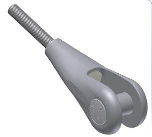
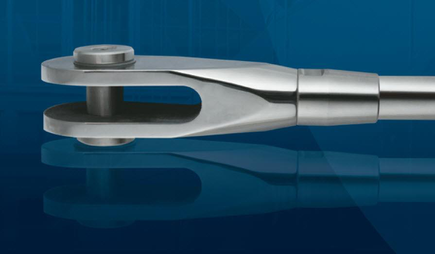
Examples of tension connections with good aesthetics
|
|---|

Measured bending effects are called “bending moments” and so the word “moment” gets a new specialized meaning in addition to the usual non-technical one! When anything is being bent the action is trying to twist or rotate so it is not surprising that the units for Moments are the same as for torque – the Newton-metre: Nm (N x m = force x lever arm distance). 1Nm is the moment or rotation exerted by a force of 1N (100g under gravity) acting on a handle 1m long – or 0.5N x 2m, or 2N x 0.5m, etc. Balancing persons of different mass on a see-saw is the same principle.
Max M (kNm) is at midspan = P (kN) x L (m) ÷ 4
Max V (kN) is at the supports = P (kN) ÷ 2
Max d (mm) is at midspan = P (N) x L3 (mm) ÷ (48 x E (MPa) x I (mm4))Simply supported, single span (L) beam with a UDL (w) over full span:
| Max M (kNm) is at midspan = w (kN/m) x L2 (m) ÷ 8 Max V (kN) is at the supports = w (kN/m) x L (m) ÷ 2 | |
|---|---|
| Max d (mm) is at midspan | |
|
||
|---|---|---|
 |
||

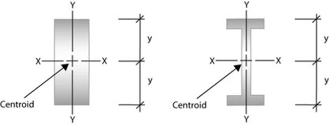
These properties are used to determine the ability of the shape to perform under loading. They are:
|
|---|
|
|---|
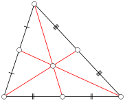
Method of determining the centroid of a triangle
|
|---|
How to Find the Centre of Mass of an Asymmetric Beam (‘T’-Beam, Channel-Beam, Angle-Beam)
‘I’-beams and rectangular beams are symmetric along both axes, thus their centres of gravity
Finding the exact location of the centre of mass can be tricky for complex shapes. Luckily, if you
can partition the cross-sectional shape of the beam into rectangles, you can easily find the x- and
Label the lengths and widths of edges.
(2) Divide the figure into several smaller rectangles. There may be more than one way to do
The x- and y-coordinates of the figure's centroid are weighted averages of the centroids of the smaller rectangles.
Example 1: ‘T’ Section-Beam
|
|---|

The second moment of area is also known as the moment of inertia of a shape and it is directly related to how stiff (resistant to deflection) the beam section is when bending. It is very sensitive to overall section depth and to the parts of the cross section most remote from the N/A (neutral axis).
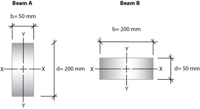
For Beam A above the Ix value (for bending about the horizontal axis in the direction the load is applied):
|
|---|
This means that for the same span and the same loads Beam B would deflect 16 times further than Beam A because a beam deflection equation depends mainly on Load x Span3 ÷ (E x I).
Consider Beams A and B are timber with material stiffness E = 10,000MPa and 3m simply-supported spans with load P of 2kN acting at midspan.
Equation for this beam: Deflection = P x L3 ÷ (48 x E x I).
Section modulus is a geometric property for a given cross-section used in the design of beams or flexural members. Other geometric properties used in design includefor tension,for compression, andfor stiffness. Any relhip betwees is highly dependentuestion.
Elastic Ss can also be defined as the first moment of area.
|
||
|---|---|---|
 |
|
|

| doubly symmetric (strong ax |
|
||||||||
|---|---|---|---|---|---|---|---|---|---|
| doubly symmetric (weak axi | |||||||||
|
|||||||||
|
 |
||||||||


|
|---|
The Plastic section modulus is used for materials where elastic yielding is acceptable and plastic behaviour is assumed to be an acceptable limit. Designs generally strive to ultimately remain below the plastic limit to avoid permanent deformations, often comparing the plastic capacity against amplified forces or stresses.
|
|
|
|---|---|---|
|
||
|
|
|
|


The plastic section modulus is used to calculate the plastic moment, Mp, or full capacity of a cross-section. The two terms are related by the yield strength of the material in question, Fy, by
It is based on the idea that most of the work in bending is being done by the extreme fibres of the beam. To calculate Z, the distance (y) to the extreme fibres from the centroid (or neutral axis) must be found as that is where the maximum stress could cause failure.
Z for Beam A = 50 x 2002 ÷ 6
= 333.3x103mm3
Z for Beam B = 200 x 502 ÷ 6
= 83.3x103mm3
Bending stress for Beam A = M ÷ ZA
= 1.5x10⁶ ÷ 333.3x103
= 4.5MPa

|
||
|---|---|---|
| 9.0 | ||
The primary job of footings is to receive what often intense structure loads are from above and then decrease the compressive stress to a level that the soil conditions can support usually by increasing the width over which the structure loads are spread.
Footings commonly also allow concentrated loads to spread out longitudinally by having the footing behave as a beam which also protects the structure if any differential settlement occurs. As any soil conditions become stronger, the footings can be less substantial.
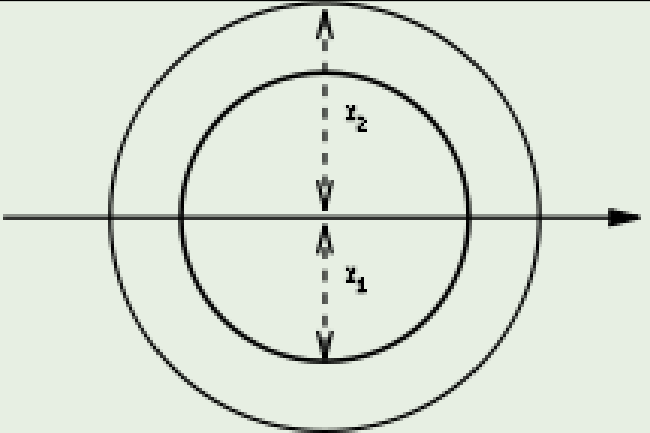
The radius of gyration is used to compare how various structural shapes will behave under compression along an axis. It is used to predict buckling in a compression member or beam.
The smallest value of the radius of gyration is used for structural calculations as this is the plane in which the member is most likely to buckle. Square or circular shapes are ideal choices for columns as there is no smallest radius of gyration. They have the same value because the radius is constant.

The gyration radius is useful in estimating the stiffness of a column. If the principal moments of the two-dimensionalare not equal, the column will tend toaround tsmaller principal moment.
Mass moments of inertia haveof[mass] × [length]2.
It should not be confused with which is used in bending calculations.
The most efficient shape for a column is the circular hollow section (CHS). The second most efficient shape is the square hollow section (SHS).
|
|
|---|
Buckling is a major consideration in designing all compression members. Buckling is deformation (deflection, bending) at right angles to the direction of the applied load.
The longer and/or more slender the member, the
more likely it is to buckle under compressive
|
|---|
The tendency to buckle also increases with the strength of the material. As the material gets stronger, the cross-sectional area required to carry the stress decreases. This produces more slender struts which are more likely to buckle.
|
|---|
Slenderness for the cross-sectional area of general shapes is calculated using the following formula:
|
|---|

= maximum or critical(vertical load on column),
=
= 0.50. For both ends fixed,
For one end fixed and the other end pinned,= 0.699....
For one end fixed and the other end free to move laterally,
= 2.0.

The way in which a column buckles is affected by how rigidly it is connected to other members at the top and the bottom. The term for the type of end fixing is end fixity and this affects the way a column buckles.
|
|---|

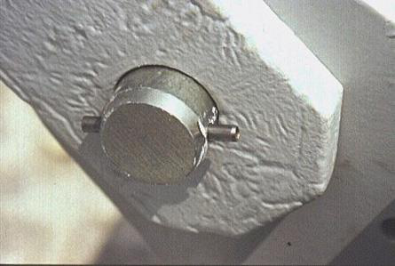
When a column end is connected in such a way that the joint allows the column to rotate freely but restrains it from translation (horizontal movement), the connection could be described as being pinned. Such a joint could be produced in practice in several ways.
The end conditions influence the shape of the buckled form; the effective length corresponds to that part of the column which deforms as a single curve in the shape of a pin ended buckle.
The type of end condition will dictate how much restraint to lateral buckling is offered to the column. The pin ended column can buckle more freely than a fixed ended column and is therefore less strong.
|
|---|

| 1. | Type A column is encased in a concrete at the top | |
|---|---|---|
| 2. |
|
|
|
||
| 3. | ||
| Type C column has a pinned joint at the top and is | ||
| 4. | fixed at the bottom. The bottom third of the column | |
|
||
| Type D is pinned at the bottom with no fixing at the | ||
| top. This is an extreme case, e.g. a flagpole which | ||
|
||
Pcr = π2 x E x I / Le 2 = π2 x 10000 x 2.1x106 / 40002 = 12950N = 12.95kN
If noggins are installed then the weak direction Le is halved to 2m and increased Pcr = 51.8kN In the stronger direction Pcr = π2 x 10000 x 33.3x106 / 40002 = 205400N = 205.4kN
Review the HIA Student Accommodation Project and identify as many structural elements as you can that are have compression forces acting on them.
Explain what loads are creating the compression forces.
|
|---|
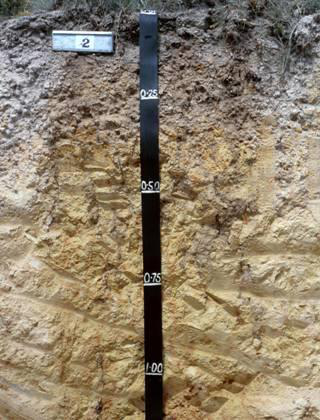
Typical Clay Soils
|
|---|
The soil type between clay and sand (0.002 – 0.06mm) is silt and it is not good founding material with certain risks where high moisture content and vibration loads are involved. The cement particles in concrete are the size of silt which is why fresh concrete reacts the way it does to vibration – a useful property we exploit to aid its placement and eventual strength gain.
The main engineering property desired from soil in structures is compressive bearing strength with values varying from as low as 50kPa for soft clays right up to concrete-like strengths of 20MPa and more for solid rock. This property is significantly affected by how compact or dense the soil is by removal of void space (if density ↑ then strength ↑) and, in cohesive soils, the moisture content (if moisture content ↑ then strength ↓). In natural or in-situ soil the bearing capacity generally increases with depth. The typical failure mode for soil is to allow excessive settlement of the load application point, which means that soil particles must be moving past each other.
|
|---|
| covers - | • |
|
|---|---|---|
| • |
|
|
| • | ||
| • | ||
| • | ||
| • | ||
| • |
|
|
|---|
It is important not to confuse the Material Stiffness of concrete (E value) with the compressive strength. These two values use the same unit (MPa) but apply to different characteristics of the materials.
The E value is how strong the material is in bending whilst the compressive strength is how strong the material is in bending.
The key aspects of concrete behavior and how it can be influenced by site operations are:
The mix design for any concrete is critical to achieve the intended properties in service. This covers quality and size of the coarse and fine aggregates, cement type, and proportions of these
as well as for the required water to start the chemical reaction of “hydration”. Other chemicals for
Roughly 5% of achievable strength is lost for every 1% of air by volume left in the concrete. So for in situ construction it is critical to control this.
Concrete can be over-vibrated but this is not as detrimental us under-vibration.
Concrete can be designed with exceptional durability and an almost indefinite service life. There are many Australian Standards relating to concrete (raw materials, sampling, testing, etc.) but the primary one referred to by designers is AS 3600 for concrete structures.
|
|
|---|---|
|
|
| o | |
| o | |
| o | |
| o | |
| o |
|
| o |
|
| o | |
| o | |
| o | |
Engineers include specialists in a number of fields including:
|
|---|

o Preparing reports on how to protect neighbouring properties.
o Preparing dilapidation reports.
Structural Steel Detailer
o Prepare detailed shop drawings for the manufacture and erection of the steel
o Complete shop drawings show material sizes and dimensions of the steel members to
be used (such as beams, columns and trusses) as well as welding, bolting and surface
widespread global use. It is mainly iron, which is alloyed
with small percentages of carbon and often other
include 300MPa for hot-rolled steel sections (e.g. UB,
PFC), 450MPa for cold-formed hollow sections (e.g.
|
||
|---|---|---|

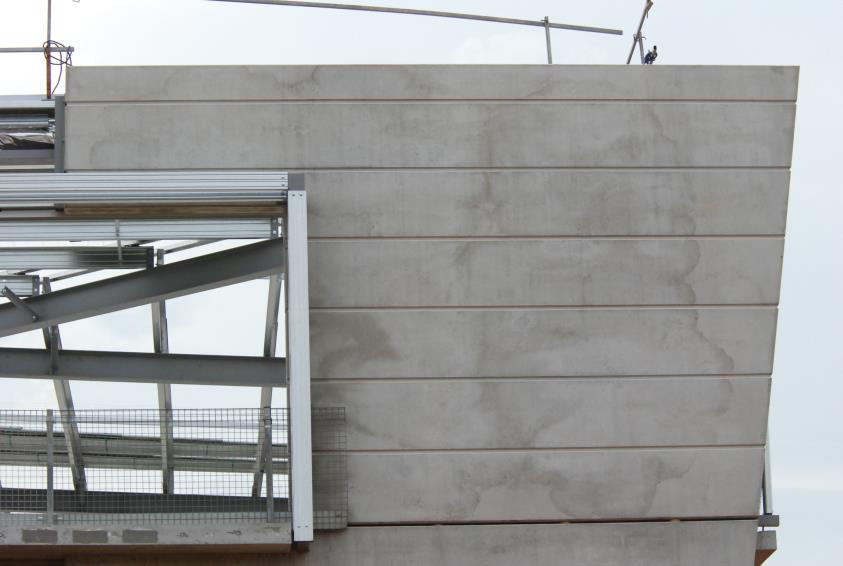
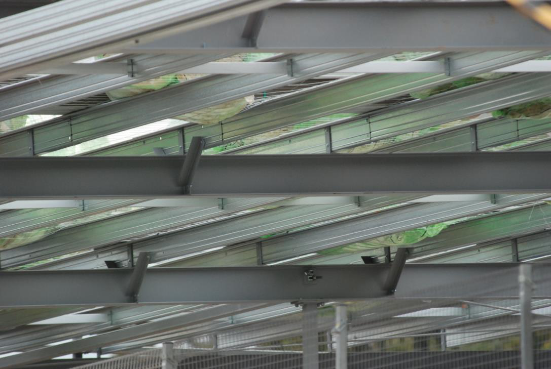
Steel frame braced by pre-formed concrete panels
Galvanised and painted structural steel – note the fly bracing to the beams

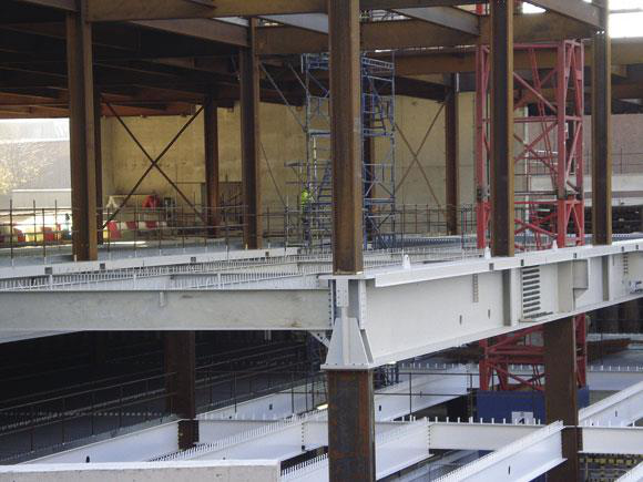
By using steel reinforcing within the concrete, the steel provides the strength in tension, bending and shear whilst the concrete provides the compressive strength as well as hold the reinforcing in place under substantial loads.
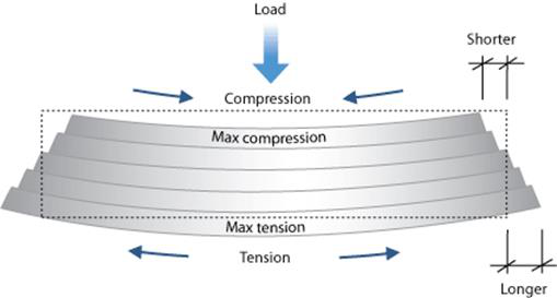
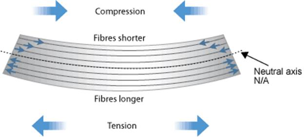
If we look at our simple beam example, we can see that when a load is applied to the top of the element (in this case a beam) the top is in compression and the bottom is in tension.
|
|---|
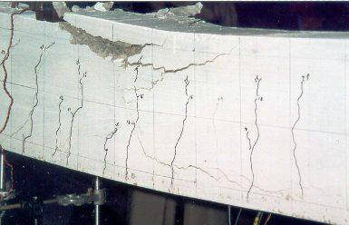
Note in the second image, the reinforcing that is under compression along the top of the beam has
o Footings.
o Ground Slabs.
o Tilt up Panels.
o Pre-cast Beams.
on the site.
|
|---|
plywood, chipboard, LVL. Once the minimum properties of any timber are established it can be safety designed with. One of the chief benefits of timber in construction is that it is easily workable on site and very safe to do so.
Commonly available timber strengths or the allowed stress designed for can vary from 4MPa (F4) up to 27MPa (F27) or more if rated appropriately. Material stiffness (E) varies widely and often in proportion to the strength, as exploited by the MGP grading system. Density also varies widely.
The two basic divisions of timber are hardwood and softwood and from a structural perspective, hardwood is usually stronger than softwood. Technically speaking, the names hardwood and softwood have no real bearing on their strength or hardness, as timbers are divided botanically into the two classifications with softwoods being coniferous or cone bearing trees having needle like leaves and hardwoods being relatively broad-leaved trees with seeds produced in an enclosed form such as a fruit or nut.
However, the commercial use of structural timber sees hardwoods used for high strength applications such as bearers, joists, lintels (window and door opening beams), roof beams etc and softwoods used for general framing i.e. studs, wall plates, noggins, rafters and other such
applications where high strength is not the critical factor.
Other structural applications like bridge and wharf timber, pre-assembled trusses and frames, building poles and other engineered timber components are readily available and may be suitable for your building project. Timbers of these types would need to be specially selected for their application or would be graded or made to order depending on the requirements of the builder and/or designer. The supplier in the case of engineered timbers or trusses and frames would need to see copies of plans and specifications.
Often the strength-to-weight ratio of structural aluminum is rightly praised in comparison to steel but the stiffness-to-weight ratio is about the same for both, and if strength-to-price and stiffness-to-price is considered then aluminum alloy is relatively expensive.
With the wide use of heat-treated alloys any welding has to be undertaken carefully.
In some ways demolition is a more challenging engineering exercise since it is often the case that no or insufficient design information is available to assess and manage the structure being demolished.
As demolition takes place, the structure becomes unstable until fully demolished. In many instances, temporary support structures need to be put in place to support a structure during demolition.
Where these structural elements are required, they will be engineer design to ensure they can meet the load requirements to support the structure.
|
|---|
Demolition work is to be carried out in accordance with Australian Standard AS2601: The demolition of structures (AS 2601). If the work is not covered by or included in AS 2601, the work must be done in a manner acceptable to the local safety regulatory authority. As compliance with AS 2601 is usually mandatory, the content and safety and health issues covered in the AS 2601 are summarised below:
AS 2601 - The demolition of structures:
• safety and health issues are addressed under the headings of:
o Health and safety of the public - covering general requirements, lighting, falling materials, fencing, hoardings and warning notices, scaffolding, overhead protection for footpaths, and hazardous materials and conditions;
Some regulations require a copy of AS 2601 to be at every demolition site whilst demolition work is being carried out, except where the thing to be demolished is a fence or wall less than 1.8 metres in height or a building or structure less than 2 metres in height.
|
|---|
Planning is key to the planning of the demolition process. Each jurisdiction has its own
requirements prior to demolition work commencing and often these local regulatory authorities require a documented demolition plan. There may be time considerations where these plans may have to be lodged for some specified time before work can actually start on site.
In planning demolition, AS 2601 “The demolition of structures” should be consulted and depending
Communication
When communicating with the various stakeholders in a building project and in particularly the demolition of a structure, certain techniques and considerations could be used to account for cultural and language differences amongst these parties. These include and are not limited to the following:
o Use of translators.
o Cultural awareness.
These considerations will be included in a Project Safety Management Plan based on the relevant Australian Standards and relevant local safety legislative requirements.
| o |
|
| o |
|
| o | |
Generally used for structures with only a few storeys. Using heavy machinery, the demolished structure is “dragged” and collapsed into the internal area of the building envelope.
As the structure is collapsed, the debris is removed from the demolition area and the site.
|
|---|
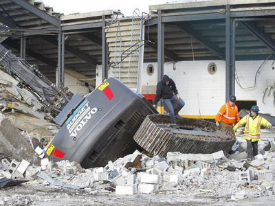

Some structures and some parts of structures are demolished from the top down. This process
involves placing machinery on top of the structure and demolishing section by section and level by level until the structure is completely demolished. In order to demolish structures in this manner, the structure must be assessed for adequacy to
support the load of the machinery.The actions of the machinery in carrying out the demolition must also be taken into account. An excavator weighing 6 tonnes with a lifting capacity of 10 tonnes is capable of applying a load weight of 16 tonnes to a structure it is working from.
This is a spectacular but high risk method of demolition. Often carried out with great success but there have been some serious failures as well.
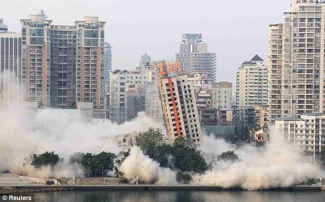
One such failure was the demolition of the Canberra Hospital in 1997 when an attempt at implosion demolition failed. One onlooker was killed and several were injured by flying projectiles from the explosions. The building did not collapse and was unstable, making the subsequent demolition far more difficult and dangerous.
|
|---|
A1.1 Legal
(a) Has Development Consent being obtained?
• PCB’s,
• Lead paint,
(g) Are the tender/contract documents sufficient and complete? (See Appendix B of AS 2601 for further information).
A1.2 Structural
|
|---|
(a) Identify and locate service supply mains (water, electricity, gas) and extent of
reticulations; NOTE: If no services drawings are available, a services search company may need to be employed to locate all above- and in-ground services.(b) Identify and locate emergency services (fire detection and fire-fighting); and (c) Establish nature, location and extent of other services (sewerage, drainage, air-conditioning, lifts).
(e) Determine most suitable points of egress from the site for -
(i) Site personnel; and
(ii) Demolition equipment and routes for removal of demolished materials.(f) Examine and record the condition of buildings on the adjoining sites, particularly where these abut a common boundary.
(c) From the level-by-level procedure, determine nature, number and sizes of mechanical equipment, and number and skills of personnel to be deployed on the working level.
(d) Obtain advice from a structural engineer on whether structure of working level can safely sustain proposed loads, and if not, modify proposed procedures accordingly. (e) Ascertain what restrictions are imposed on working hours, use of public thoroughfares, noise level, and the like.
(d) Establish amenities.
(e) Fully inform all site personnel of the work plan, and safety procedures, and establish procedures for dealing with emergencies (accidents, fires).
(b) Any temporary bracing, shoring, or propping is tight, stable and secure.
(c) All fire and safety services are operational and all other services to the working level have been properly disconnected.
(b) All demolished materials have been removed or secured against inclement weather. (c) All fires or embers have been properly extinguished.
(d) All emergency access routes are clear of debris and clearly marked.
|
||
|---|---|---|
 |
||

In small groups, review the image and drawings and produce an outline of how the demolition
would be carried out.
o Where the drop zones would be (Indicated on the site plan.)
o Where hoardings, fencing and shoring may be used.

|
|---|
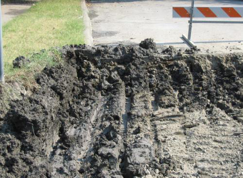
Foundations (soil used for structural purposes) are involved with all forms of building construction.
To ensure safe and expected performance from any foundation it is essential first to know about the engineering properties / ground conditions where the presence of the proposed building will interact via an appropriately detailed Geotechnical Investigation (which may also involve laboratory Soil Testing). The major potential ground response we are interested in is settlement under the accumulated vertical dead and live loads from the structure above. Foundations can settle in 2 ways – by direct increase in the density of the soil (compression compaction) and / or sliding past / through the surrounding soil (shear displacement).
|
|---|
It is a very worthwhile exercise to both check and record the testing of founding materials prior to proceeding with the construction of the footings.
 |
|---|

Identify what problems may occur in excavating the foundations and what could be done to resolve the problem.
|
|---|
Aside from the surface protection benefits of adding blinding concrete the most common improvement or fault correction for foundations is to increase bearing capacity. This can often be achieved by excavating to a greater depth since most soils are stronger as depth increases.
Bearing capacity can also be increased by compacting the soil below the founding level.
Clays (cohesive soils): Clays generally are termed “reactive” which describes dimensional response to changing moisture content (swelling / shrinkage). Some clays are more sensitive to this than others depending on the particle chemistry. Most natural clay soils are satisfactory for supporting the footing loads from houses (which are relatively light in the overall spectrum of footing loads in all structures). However, because the footing systems for these lighter structures (e.g. houses) are relatively shallow the potential for differential movements at the underside of footings is increased due to lesser counteracting building forces and more variation in soil moisture as the footing depth decreases. As the moisture content of clay increases its bearing capacity decreases.
Sands / Gravels (cohesionless soils): Sands and gravels are generally strong and stable soils on which to build with bearing capacity not so affected by moisture content as for clays. It is critical that the specified density of the soil (i.e. compaction) is achieved and that the soil is adequately contained and protected from any erosion actions (e.g. wind, water, removal by ants!).
Once you have calculated the dead load you now need to establish the live load on the footing pad for the column at D2. You should apply the values contained in the Participant Guide Section 4.
The geotechnical report has provided a bearing capacity of 100kPa for the founding materials at the depth of the footings.

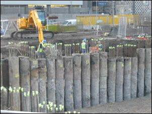
Bored piles are often used as retaining walls to hold back foundation soil from adjacent structures. This can be done in two ways:
1. |
|---|
|
|---|
Ground piles are often made from reinforced concrete but can be timber or steel.
Ground Piles come in four main types.
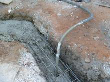
with concrete. The top of the reinforcing cage extends past the top of the pile to be connected to the slab or footing beam being constructed on top of the pile.
Piles are bored and then the cages lowered in the hole. Concrete is then poured in to the pile.

Top of the reinforcing “cage” is exposed for connection to subsequent building elements
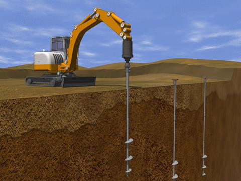
Driven piles can be timber, reinforced concrete or steel. The piles are driven into the ground using either a large drop hammer rig or high impact rate pneumatic or hydraulic hammer.
This type of piling is generally used for deeper applications where excavation would not be an economical solution. Driven piles usually gain some of their bearing capacity from friction as well as end bearing. Because the piles are required to have a narrower section in or to be driven, they are not suited to use as a retaining wall solution.
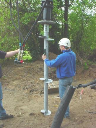
Screw piles or helical piles are like and auger that is left permanently in the ground. The piles are screwed in with a hydraulic auger driver and left as a footing for further construction as with driven piles.
 |
 |
|
|---|---|---|
| reinforcing bar welded to it is bolted | ||
|
||
| concrete elements are formed over | ||
| the top of the plate incorporating the | ||
|
||
|
|---|
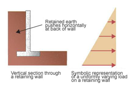
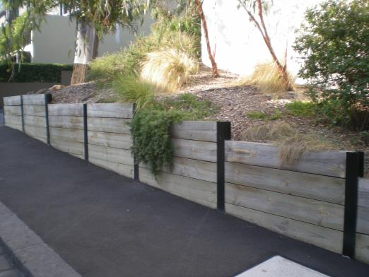
Gravity
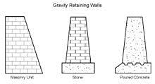
concrete units (masonry units).
|
|---|
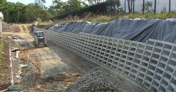
Earlier in the 20th century, taller retaining walls were often gravity walls made from large masses of concrete or stone. Today, taller retaining walls are increasingly built as composite gravity walls such as:
o Geo-synthetics such as geo-cell cellular confinement earth retention or with precast facing;
o (stacked steel wire baskets filled with rocks);
o s (cells built up log cabin style from precast concrete or timber and filled with granular material); or
o Soil-nailed walls (soil reinforced in place with steel and concrete rods).Cantilevered
walls may be buttressed on the front, or include a counterfort on the back, to improve their strength
resisting high loads. Buttresses are short wing walls at right angles to the main trend of the wall.
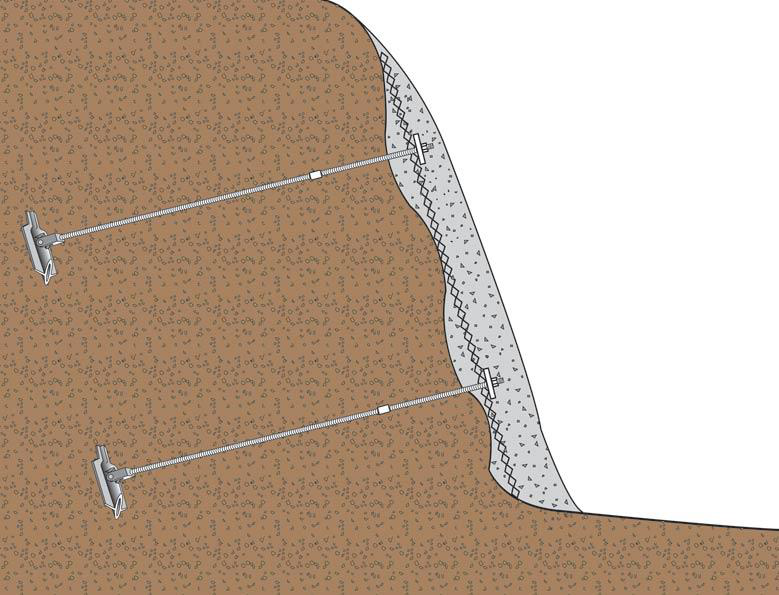
Anchored
An anchored retaining wall can be constructed in any of the styles discussed elsewhere, but also includes additional strength using cables, tiebacks or other stays anchored in the rock or soil behind it. Usually driven into the material with boring, anchors or tiebacks are then expanded at the end of the cable, either by mechanical means or often by injecting pressurized concrete grout, which expands to form a bulb in the soil. Technically complex, this method is very useful where high loads are expected, or where the wall itself has to be slender and would otherwise be too weak.

Helical anchors are screwed into place. Their capacity is proportional to the torque required during installation. This relationship is in accordance with the equation Qt = kT
where Qt is the total tensile resistance,
k is an empirical constant and
T is the installation torque.These anchors are installed either for small loads in short sections or for larger loads and in long continuous lengths.
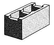
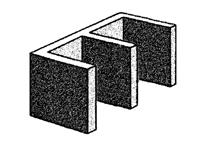
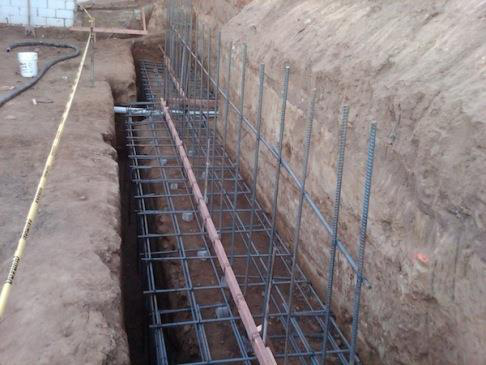
Reinforced Blockwork
Blockwork units are commonly hollow with voids large enough to fill with concrete – and termed “core filled” - (and with reinforcement) whereas clay brick units may be hollow but only with small unusable voids which are present to reduce weight, aid the efficiency of kiln firing, and also provide improved keying into the mortar joint.
|
|---|
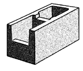


In this case of a reinforced core-filled blockwork wall it effectively behaves as a low strength but ductile reinforced concrete wall.
Filled blockwork, waterproofed and with drainage cell starting to be installed prior to back-filling.
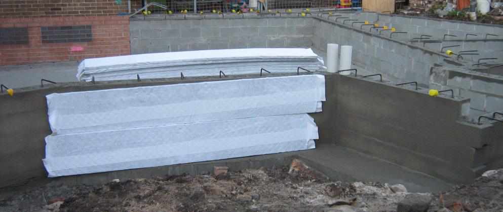
An ag. drain will be installed
|
|---|
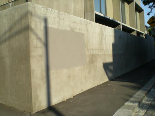
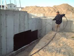
Final activity in installing a shotcrete retaining wall – tie-in and reinforcement can be seen to the left
What is shotcrete?
Aesthetically it is far better (and more cost effective) to apply shotcrete precisely to unstable sections of cuttings than to apply a blanket covering. In order to achieve this, the shotcrete application should be planned and designed in advance so as to minimise visual impact as well as stabilise the slope.
|
|---|
Unlike cast-in-place concrete, the success in applying shotcrete is mostly dependent on the skill and experience of the shotcrete installation crew, especially the nozzleman. The nozzleman is the person controlling the nozzle that delivers the concrete to the surface.
The inspection process should include substrate preparation, steel reinforcement (position, size and anchorage), shotcrete material quality, mixing of materials, equipment operation and gunning technique, encapsulation of steel reinforcement and proper curing.
The AB Collection is easy to install. These blocks are dry-stack without mortar or footings. The hollow core feature makes them easier to handle and promotes good drainage behind the wall. The raised lip and notch lock each block in place and creates a natural setback. Use one sized block or mix the different block sizes together in the wall to capture the look of hand laid stone. The AB Collection is right at home in residential settings where retaining walls 6’ and under are typically called for, and up to the task on larger retaining walls 6’ and over.
Evaluate structural requirements
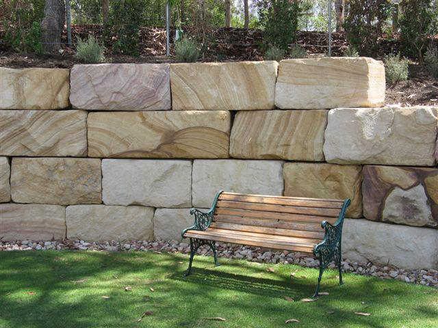
Concrete Block Retaining Wall Systems
Retain sloping land or create a free standing feature garden wall with retaining wall blocks.

Convict sandstone retaining wall, Sydney
|
|---|
|
Refer to the HIA Student Accommodation Project. |
|---|
|
|---|
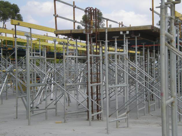
As part of the management of the construction process, many temporary structural elements will be put in place to temporarily support the permanent structure and then removed when no longer required.
Often referred to as “Temporary Works” this can include such things as shoring, formwork, bracing and the like.
|
|---|
Various Regulations for construction OHS/WHS require the input of specific Construction Engineers in addition to the Project Design Engineer to address these tasks.
|
|---|

|
|---|
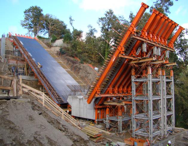
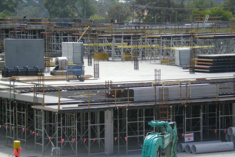
Formwork refers to the sheeting and framing that is used to form the reinforced concrete elements such as suspended slabs, beams and the like that are going to be poured.
|
|
|---|
|
|---|

Further, because it is a liquid, the load it applies is varying and shifting. If a bucket is released on a section of formwork for a slab for example, the concrete will sit in a mound at that point until spread. That load can be more than twice the eventual load of the wet concrete over the entire structure once spread and screeded. Also, as the concrete is released from the bucket it generates forces of inertia which will be applied to the formwork where the concrete lands.
This is particularly prevalent for columns where the concrete will fall three metres or more before it makes contact with the formwork.
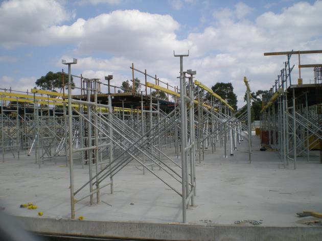
Formwork is usually very open and is often well above the ground which makes it more susceptible to wind conditions.
Loads on formwork and false work must be considered in three stages:
|
|---|
Design requirements for Formwork and False Work are detail in AS3610-1995 Formwork for Concrete.
The components can be assembled in accordance with AS 3610 or can be an engineered proprietary system that has been designed by a supplier.
|
|---|
With larger projects, the use of “Formply” sheeting is more common because the sheeting can be used in multiple locations or on multiple levels because on large structures the whole structure is done in multiple stages. For small projects where there are only two or three levels, the use of permanent formwork such as “Bondek” is employed.
“Bondeck” is being used in medium and high rise suspended slabs where a flat soffit is not required. This permanent formwork is relatively fast to construct and adds structural integrity to the overall structure when complete as it provides a reinforcing factor. It also provides a ribbed finish which can be compatible with hanging systems for ceilings and services.
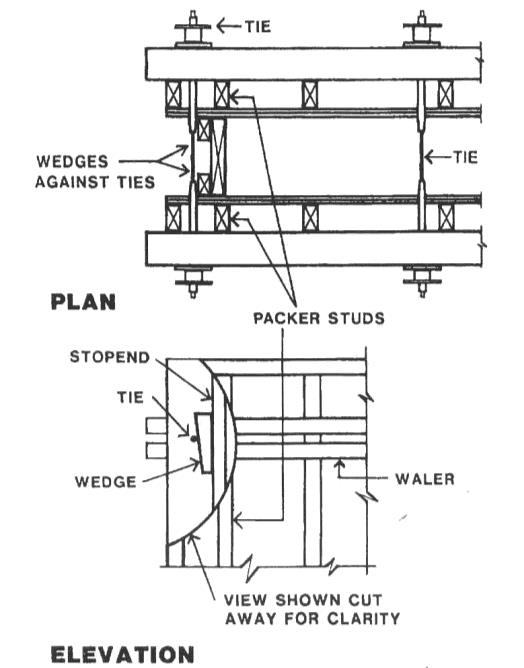
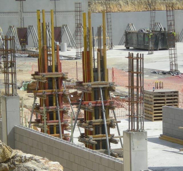
Vertical walls such as shear walls are formed
with vertical formwork and false work. The
formwork consists of sheet materials, vertical
or horizontal joists, walers and struts. The
joists are set at low centres, e.g. 300mm -
450mm to support the sheets.The walers restrain the joists, hold the ties and
have the props attached.


In calculating the total on formwork and false work we measure the load in kPa in the same manner that other loads are calculated. In order to design a formwork with sufficient load resistance we need to consider the following points:
Calculation of concrete load:
Other components of the total load are generally considered to be as follows:
|
|---|
For the example above of a 300mm thick slab, if the props or frames are set out on a 1800 x 2400 grid then the overall load on each prop/frame plate will be:
67.39 kn. (4.32m² x 15.6kPa) of force on each prop.
This would be done by use of sole plate. Sections of timber that are “stacked” under the prop plates to “spread” the load across a much wider area of the founding materials.
|
|---|
|
|---|
There have been several recent incidents where formwork has failed during concrete pours. Formwork failure can result in concrete blowouts, falling formwork components or structural collapse, and has the potential to cause death or serious injury.
Formwork failures are often caused by:
• removal of formwork before the concrete achieves adequate strength
• overloading of the formwork during concrete pouring operations.
Erecting formwork
Ensure a competent person produces a formwork design capable of supporting the expected dynamic and static loads.
• ensure the designer inspects the formwork and verifies the changes don’t compromise the structural integrity of the formwork.
Pouring concrete
|
|---|
1. Has the formwork system been properly designed?
A competent formwork designer and/or formwork manufacturer/supplier should design the site formwork system. The formwork contractor should have erection design drawings and
specifications for the particular formwork system to be constructed. Ensure a copy of the design drawings and loading calculations are available on site. Make sure the building's design engineer specifies when the formwork can be dismantled (concrete cure requirement).4. Is steel fixing being done safely?
Make sure plastic protective caps are always placed on the ends of starter bars to safeguard workers. When fixing steel for concrete walls and columns, steel fixers will need properly constructed scaffolds. Steel fixers need protective glasses when using bolt cutters to stop steel fragments from wounding their eyes.
|
|---|
8. Are concrete pumps being used safely?
Concrete pumps must be well maintained, fully serviceable and should comply with the
requirements of the Industry Standard for Concrete Pumping. The operator of a truck mounted concrete placing boom must hold a WorkSafe certificate of competency (Class PB). Ensure mobile boom-type units are set up correctly and fully comply with the NO-GO-ZONE rules for overhead power lines. Concrete pumping lines need cleaning out after each use.11. Are the concreters working safely?
Make sure there are no open sides or penetrations where a worker could fall. Where required, provide temporary guard-rails or a heavy duty perimeter scaffold.
From the HIA Student Accommodation Project, discuss the following:
|
|---|
The significant considerations involved with scaffolding include:
|
|---|

Scaffolding work that involves scaffold from which a person or object could fall more than four metres is classified as ‘high risk work’ under the WHS Regulations for which a licence is required.
Scaffolding licence classes are as follows:
Scaffolding plan
An effective plan will help identify ways to protect persons who are:
|
|
|---|
The design of the scaffold should take into account:
Dead loads relate to the self-weight of the scaffold structure and components including any working, catch or access platforms, stairways, ladders, screens, sheeting, platform brackets, suspension ropes, secondary ropes, traversing ropes, tie assemblies, scaffolding hoists or electrical cables.
Live loads include:
|
||
|---|---|---|
Supporting structures
Consider the capability of the supporting structure to bear the most adverse combination of loads possible during the use of the scaffold. Obtain advice from a competent person before erecting scaffolds on verandas, suspended flooring systems, compacted soil, parapets and awnings.
The size of the soleplate will vary depending on the supporting surface. Where necessary a competent person should determine the bearing capacity of the ground or other supporting structure.
Soleplates should be level and some digging may be required to obtain a level surface.
Stability
Procedures must be developed for the inspection and maintenance of the scaffold and scaffolding components to ensure that the scaffold is safe to use and remains in a safe condition. The inspection of scaffolds and scaffolding components at a workplace is particularly important when the scaffold is in place for a prolonged period of time.
The frequency of inspections may vary depending on weather and workplace conditions, the type and size of the scaffold and the risks associated with scaffold collapse.
|
|---|
|
|
|
|
|
|
|
|
|
|
|
|
|
|
1. Scaffold vicinity
Has public protection been provided?2. Supporting structure
Is the supporting structure in good condition? Does the supporting structure have adequate strength?
3. Soleplates and baseplates
Are there sufficient soleplates? Are the soleplates of suitable material and in a serviceable condition? Are the soleplates secure?
4. Scaffold structure
Are the standards bearing firmly? Are the standards plumb (or as designed)?
Are the ledgers continuous (or as designed)?
Are the lift heights correct?
Are the transoms/putlogs correctly positioned and secured?
Is the bracing adequate?
Are catch platforms correctly positioned?
Are the platforms and supporting scaffold constructed for the appropriate duty live loads? Are the platform dimensions suitable for the intended work?
|
|---|

7. Containment sheeting
Has the scaffold been designed for wind loading on any containment sheeting? Are the fixing ties secure? Are there any rips or tears?
9. Mobile scaffolds
Is the supporting surface hard and flat? Is the area of operation free of floor penetrations, powerlines and other hazards? Are the castor wheel locks in working order? They should be locked at all times, except during movement of the scaffold.
| o |
|
| o |
|
| o | |
| o | |
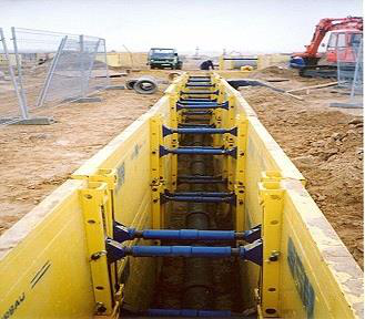
Closed/Open sheeting
Generally timber trench shoring that is either fully closed or has gaps between the shoring timbers. Very labour intensive and difficult to accurately engineer making it an unacceptable risk on construction sites. Not commonly used in construction for this reason.


|
|
|---|
Next, a check is required that all the proposed features can be located as described in the design especially the planned construction, site worker facilities, access and storage space, required plant such as cranes.
|
|---|
Poorly located site amenities will impede works on the structure as well as limiting access for heavy plant and deliveries.
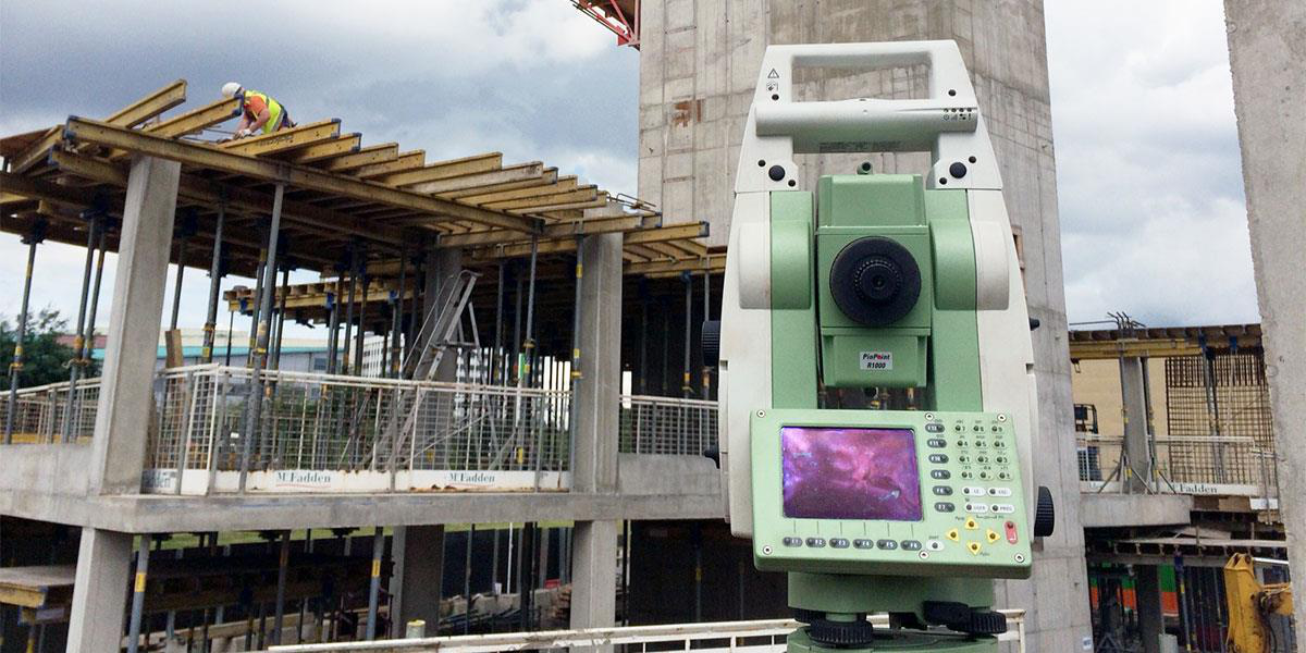
In multi-storey work such as medium rise construction, accurate set-out of levels is as important as accurate location of the structure.
The design levels for a given building will affect such things as hydraulics for drainage, structural requirements for retaining walls and access and egress grades. These must be documented and communicated effectively.

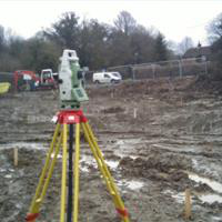
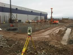
Equipment used for site set-out can be as simple as string lines and a “dumpy” level, a theodolite, or more commonly a “total station” survey device.

 |
|---|
|
|
|
|---|---|---|
| • |
|
|
| • | ||
|
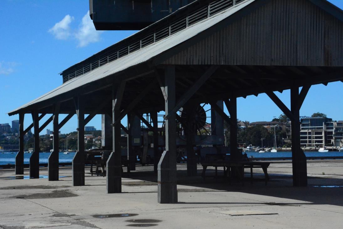
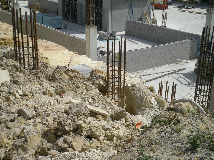
|---|
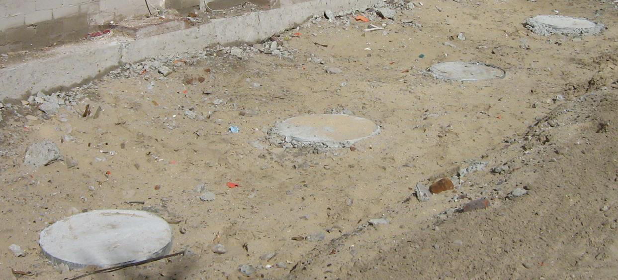
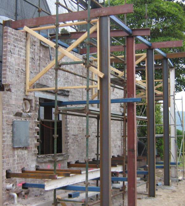
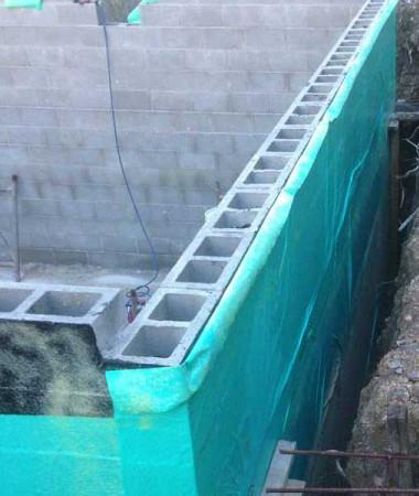
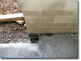
The primary role of footings is to manipulate the relatively intense forces (usually downwards) and stresses (usually compressive) that end up at the base of a structure - usually to distribute them and reduce stresses before transfer to a usually weaker set of soil conditions.
Images that follow show mass concrete footings in ‘P’ Class soil which have been used to support a temporary steel frame to support a masonry wall which had to be retained for design needs. The mass concrete spreads the load of the temporary columns and structure due to their area of bearing
|
|---|
Liners in place for mass concrete footings
Another uncommon but, at times, useful form of mass concrete is a “No fines” mix in which there is no or very little sand. It has low strength but is intended to be extremely porous and not allow ground water pressure to develop.
|
|---|
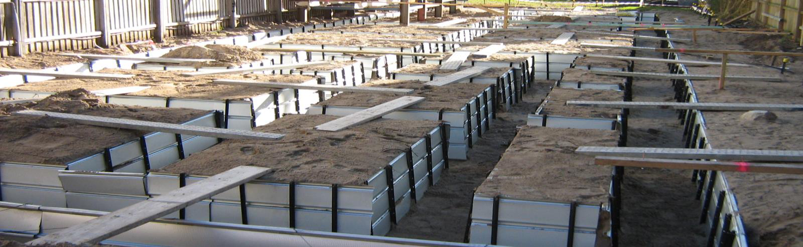
A more extreme example of this is that of the waffle-pod system which effectively creates a grid of intersecting and deep strip footings (beams) which are therefore structurally strong and stiff. The slab over is more of a capping, which is usually not working very hard as a spanning slab between the beams due to low loads and short spans.
 |
|
|
|---|---|---|

|
|---|
Damp proofing inis a type of moisture control applied to building walls and floors to prevent moisture frnto the interior spaces.problems are one of the most frequent problems encountered in residential constructt not so in medium rise.
Damp proofing is accomplished several ways including:
Concrete walls and floor
|
|---|


Intersection of vertical and horizontal DPC’s
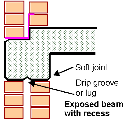
Detailed cross-section of slab bearing on external cavity masonry
Whenever a floor beam or slab crosses a cavity, such as when both leaves of a loadbearing wall are supported at each floor level, a flashing and weep-holes are needed in essentially the same configuration as a wall supported on a ground floor slab.

Where the slab bears across the top of a cavity, a drip must be cast into the slab soffit at the cavity. This can be achieved by using a proprietary folded sheet metal detail as shown in the following photograph. Obviously a slip joint has to be provided where the slab is supported by a clay brick masonry wall.
Whenever brickwork needs to be returned into the reveals to close the cavity, a vertical flashing is used to maintain its integrity. The vertical flashing is arranged under the head flashing and over the sill flashing, to keep all water moving outwards. It is preferable to make use of wider window frame sections, extended storm moulds, or internal reveal linings to allow a full-width cavity all around the opening, rather than partially closing it.
The right hand sketch above shows the external brickwork returning to meet the internal (dry) skin and includes a vertical flashing. This detail can occur where external walls return into internal walls.
Builders need to be alert to this building problem and employ this detail. What in fact is installed is a ‘vertical’ DPC at this junction. If the bricklayer will not install this flashing in one piece, care should be taken in the manner pieces are installed and their correct overlap.
A coping like that shown in the diagram should have drip grooves under each edge, to force water to drip clear of the wall. If the material is waterproof (precast concrete, or a metal sheet formed to a similar profile) a DPC should not be required underneath it; but a DPC is needed under a brick or stone coping because it is porous.
Given that the HIA Student Accommodation Project has part of a floor below ground level, the location of the termite barrier will have to be carefully determined.

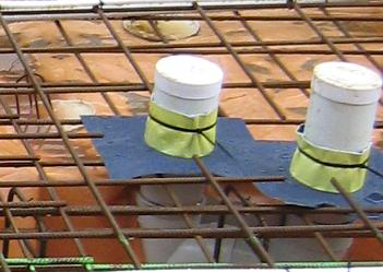
Pipe penetrations of the slabs and walls will need to be treated.
The structure of medium (and high) rise buildings avoids the use of timber and termite affected materials (glass, concrete, steel, masonry), so a termite barrier may not be required for the protection of the building’s structural integrity. Timber is not used as a structural element in the HIA Student Accommodation Project.
|
|---|

 |
 |
|
In this case all the building elements of floors and core walls are acting as shear panels - in the same way as plywood bracing in a timber wall frame. The racking forces are being applied in the same plane as the floors and walls themselves.
Reinforcing is usually constructed form heavy reinforcing bars either tied or welded into a grid as opposed to the use of lighter manufactured mesh fabric.
There are three different methods of constructing lift cores in particular but including other vertical reinforced concrete building elements.
These three construction methods are:
to “box” or form the shape, hold the reinforcing in place then pour the concrete into the form.
This formwork can be done either as a one-off for a single element such as a formed retaining wall, as a standard element that is repeated such as a shear wall, or as a continuous process where the same formwork is moved upwards as the element is constructed.
Commonly, the formwork has three platforms. The upper platform acts as a storage and distribution area while the middle platform, which is the main working platform, is at the top of the poured concrete level. The lower platform provides access for concrete finishing.
Since the formwork operates independently, formation of the core in advance of the rest of the structure takes it off the critical path.
This type of construction is more mechanized and more accurate than on-site production of vertical concrete elements.
Because of the ability to control materials and production more accurately these elements can be engineered to higher specification and therefore can be lighter construction elements with more accurate structural features and finish.

Note in this photo of a pre-cast lift core the cast in supports for the associated floor slabs at the different levels.
As with all pre-cast applications, the overall structural integrity is highly reliant on the connections between each pre-cast element. The design and the onsite installation of the connections is critical to the overall performance of the structure.
Discuss the different methods of forming the lift core and how they would apply to the HIA Student Accommodation Project. Identify and discuss the advantages and disadvantages to each method for the project. Make a recommendation on which system would be most appropriate for the project.
|
|---|
|
|---|
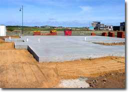
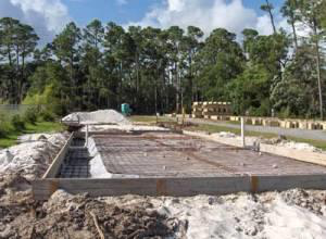
Stiffened Slab
The stiffened raft slab is the simplest and most common slab construction. The stiffened raft configuration can be used on all classes of sites (except problem sites - Class P).
|
|---|
Concrete slab on the ground
Refer to Figure 3.2.5.3(a) of the Building Code of Australia (Vol. 1).Footing slab with connection between slab and footing
The slab is connected to the footing with R10 round steel starter bars at 600 mm centres. It can only be constructed on Class A and Class S sites. The soil must have a minimum bearing capacity of 50 kPa. It is a suitable method for mildly sloping sites.
Connection between slab and footing
The concrete slab is supported by controlled fill. The controlled fill is, in turn, restrained by the
external walls which must be strong enough to contain the fill.

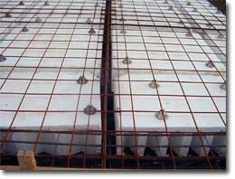
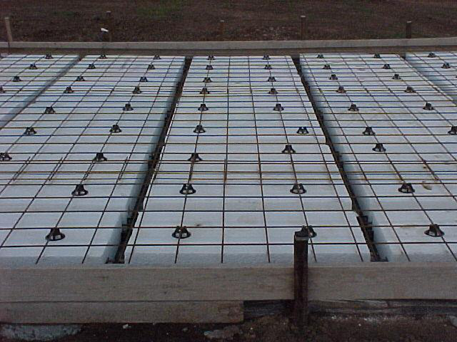
Waffle raft construction
Polystyrene void forms below reinforcement
Infill slab
Infill slabs are simply poured between existing walls, so no formwork is required. They require no external or internal stiffening beams and are typically used in garage floors where the walls are masonry.
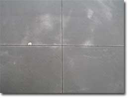
Expansion joints in the surface of the concrete slab
Concrete slab joining with brick wall
Reinforcement in rafts and slabs shall be placed in accordance with the following: (a) Minimum concrete cover for the reinforcement shall be 40 mm to unprotected ground, 40 mm to external exposure, 30 mm to a membrane in contact with the ground, and 20 mm to an internal surface.
(b) The slab mesh shall be placed towards the top of the raft or slab.
B

B
A
NOTE: The wire orientation is
Considerations
Depending on the configuration, a slab on ground will be either excavated into the founding soil and partially formed above the ground or fully formed above the ground using boxing (and void formers).

These have many variations depending on the site and requirements but generally fall into one of the three configurations.
|
|---|

In the case of ground piles and screw piles, these behave as columns and the surrounding soil acts as a “soft” buckling restraint. If any subsequent excavation around these footing types is considered (perhaps for a retro-installed basement or for drainage works?) then the effect of increasing the Le of the piles must be accounted for.
Participant Guide – Structures for Medium Rise Construction |
|---|
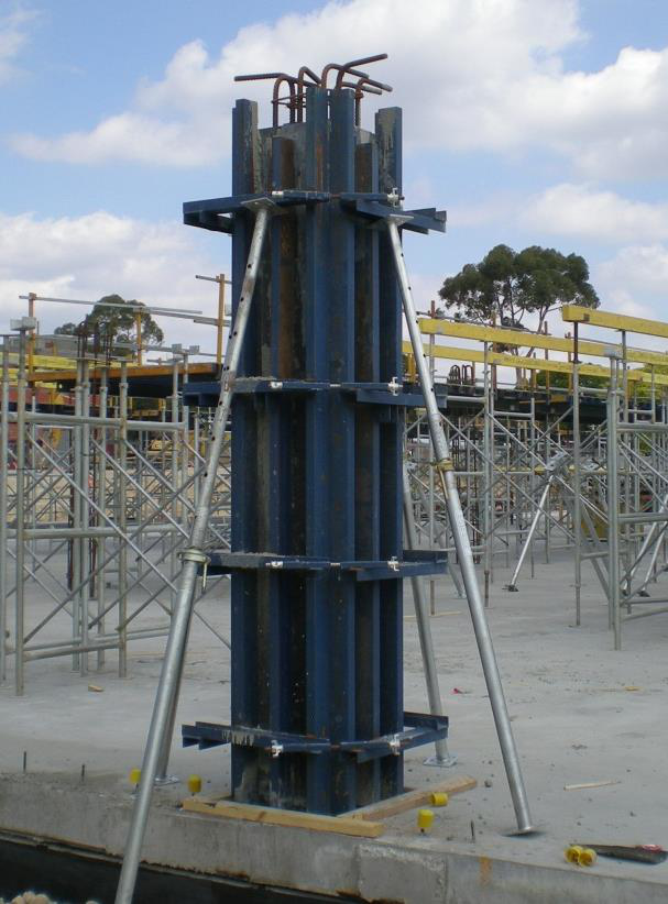
o Plywood steel framed.
They can also be plywood sheeting with metal frames or a proprietary metal form that has metal sheeting and metal framing.
Another forming method is to use either light-weight metal or cardboard form tubes. These tubes can only form round columns. They are rolled in a spiral to create a hollow tube. The tube placed over the cage and propped from the outside and the
concrete is poured.
|
|---|

Discuss what stops these reinforced concrete column cages from buckling under the significant loads they will support in service.
Discuss what stops the vertical bars in the columns from buckling and bursting out through the concrete and how.
|
|---|

To strengthen the web against this it is common practice to add stiffening plates to the web to increase the Moment of Inertia (I) of the web in the weaker direction and decrease the actual compressive stress in the web locally due to added section area.

360 = Approximately 360mm deep.
This describes a Universal Beam used generally for horizontal structural elements.
This size beam is 352 mm deep x 171 mm wide in an “I” shape. (Sometimes referred to as an “I beam”.) One lineal metre of this size beam weighs 44.7kgs.
The more on-site fabrication required the higher the cost of the steel structure because it is far more difficult to fabricate on site then in the workshop, particularly where heights are involved.
On-site/in-situ welding is also more difficult and therefore more difficult to control weld integrity. As much of the welding as possible should be done in the workshop, particularly components such as connection support flanges and the like.
|
|---|
Each of these methods has its advantages and disadvantages. Each method is suited to different applications.
Cast in situ or “Off-Form” beams are formed in the same way as suspended slabs (which will be discussed later)
The beams are boxed using formwork props and frames to support the boxing. The reinforcing cage is placed in the formwork and the concrete is poured into the boxing.
Reinforced concrete beams can certainly act as transfer beams once the loads have been designed for but with the emergence and efficiency of pre-cast panels another transfer-beam solutions, formed reinforced beams are becoming less prevalent.
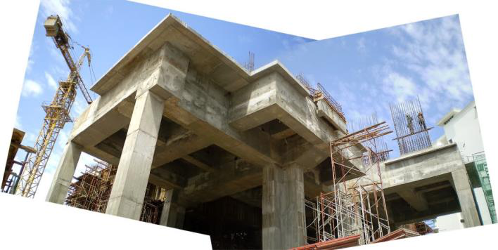
|
|---|
Pre-cast panels are very convenient deep beams for vertical load. In beam action they are quite strong and stiff so that in addition to acting as walls they can double-up for beam action and can serve the purpose of transfer beams with the appropriate design detailing.
This effect can be extended to counteract deadweight deflections so that the member need not be designed with a larger cross section (larger I value) in order to comply with specified deflection limits.
There are 3 types of pre-stressing:
The pre-stressing steel is passed through the end forms and the concrete element is cast and allowed to gain strength. After sufficient strength-gain the wires or cables beyond the element ends are cut and in trying to retract they then pre-compress the concrete. Because they are located below the centroid when they pre-compress they tend to make the element deflect upwards.
|
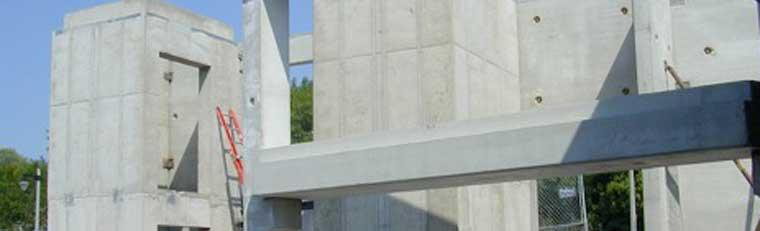 |
|---|---|
|
|---|

they can’t) but in doing so they push the duct, and therefore the entire slab, up or down depending on its curvature in relation to the strand anchor and stressing points.
Once the stressing is complete the jacked end is anchored off and the ducts injected with grout to further secure the strands and improve corrosion resistance.
The slabs or beams are formed using formwork in the same way that a poured in-situ slab and beam would be formed. The tendon ducts are laid into the formwork with the tendons installed along with the conventional reinforcing to pre-determined curved profiles. The tendons are anchored at one end and exposed at the other end.
The concrete is poured into the formed element and cured.
|
|---|
beams” are often used for these applications.
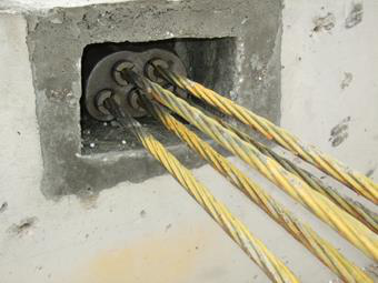
|
|---|
 |
||
|---|---|---|
|
|---|

A suspended slab however, in acting as a beam is subject to the same compression (at the top of the section) and tension (at the bottom of the section) as occurs in a beam.
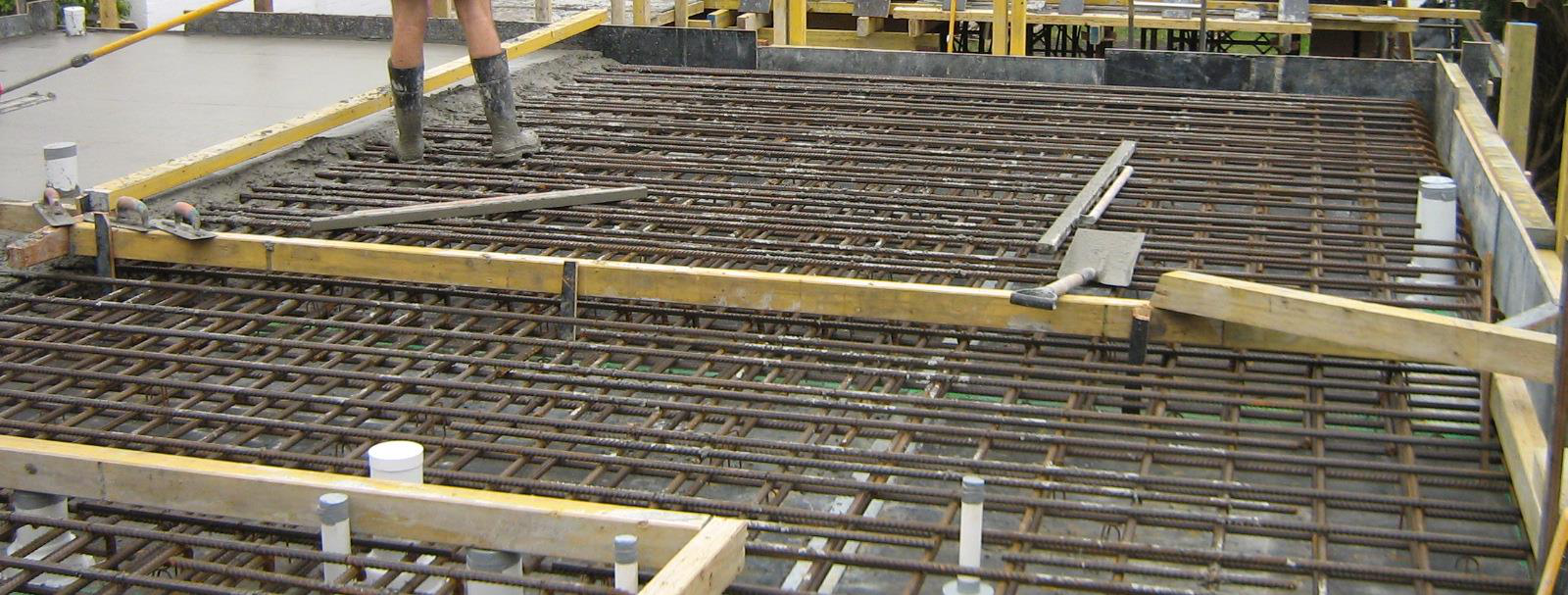
Other formwork options exist, involving permanent formwork which bonds structurally with the concrete slab, which saves the time and expense of stripping it later. Generally, formwork labour costs for in-situ concrete construction are the single biggest expense for the completed concrete element.
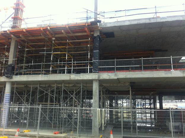
 |
||
|---|---|---|
| CLASS ACTIVITY 25 – SUSPENDED STRUCTURAL SLAB | ||

What is different between the structure in the
photo adjacent and the structure in the two photos
on the previous page considering each slab soffit
(underside) profile? What might the advantages
be for each in its floor system?
|
|---|
What is termed a “tilt panel” is just one type of pre-cast concrete – usually for a wall element – and pre-cast concrete overall is an increasing popular building form ultimately because of the commercial advantages it offers. These advantages derive from the speed of construction, and the reduced site work required.
For building works tilt-up can involve much larger panels than typically seen for pre-cast which is limited by road transport constraints.
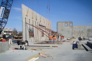
|
|---|
Note that very substantial pre-cast panels can span easily between just 2 supports near their edges so a beam action is always used.
Pre-cast panels often form support elements above openings in external walls. These panels can be in the form of a single panel that bounds three sides of an opening or a single panel that spans an opening and is mounted on the panels on either side of the opening.
Ideally there should be turning room for the trucks to avoid either reversing on or off the site. Either way this will need to be included in the site traffic management plan.
|
|---|
Panels will often be transported flat against each other. If additional bracing such as “strong backs” is required, then these will most likely be fitted when the truck has arrived at the site. As described earlier, the lifting procedure is an engineer designed process that must be carefully adhered to.
Once stood up, the panels will be braced with props. These props support the panel against wind and other construction loads during construction. They must be securely bolted to both the panel and a semi or permanent structure at ground level to provide adequate restraint in both tension and compression.
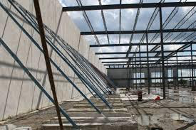
|
|---|
 |
||
|---|---|---|
 |
||
|
|---|
|
|---|
Once erected, the panels will be connected together. This will be done using plates or angles that are either bolted or welded to the panels. These connections hold the panels to each other but do not to provide sufficient restraint to hold the entire panel structure against wind loads and other construction loads. The permanent structure around the panels needs to be substantively complete prior to removing panel propping.
|
|---|
Any deemed cosmetic or surface faults with pre-cast elements are often patched on site. Major structural faults (incorrect dimensions, omitted structural items, damage during handling) might be difficult to correct without approval but there is always the option to discard the element and make a correct replacement if the program permits (not so easy for in-situ concrete construction).
|
|---|
 |
||
|---|---|---|

further complicates, but doesn’t rule out, safe design with blockwork.
In this case of a reinforced core-filled blockwork wall it effectively behaves as a low strength but ductile reinforced concrete wall.
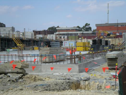
|
||
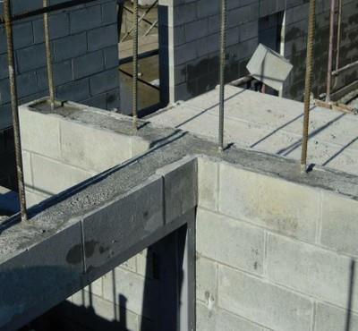
The result is a structural element carrying vertical load that is solidly tied bottom and top as well as reinforced through the centre to resist bending action from the force applied from above.
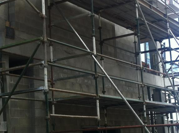

|
|---|
Roof structures are generally in three forms for medium rise construction projects:
|
|
|---|
Sheet steel roofing systems are a very common system for medium rise construction. These
systems can be constructed on both timber and steel roof frames. The sheet “tray” systems can remain waterproof at much lower roof angles (3 to 5 degrees). This means they will deliver the water to the gutters with much less hydraulic pressure which reduces the likely hood of leaking at or around gutters. Steel deck roofs are very durable and highly resistant to sun and corrosion.
|
|---|
Although membrane roof systems can be laid on steel or timber frames, they are generally applied to concrete roof systems.
|
|---|
These systems are also more susceptible to movement in the substrate because they fully bonded to the substrate.
As the name implies, these systems are laid in sheets, generally from a roll. They can be made of a variety of different materials, such as APP or SBS bitumen, PVC, butyl rubber or polypropylene.
Each has its own strengths and weakness. The
materials for bituminous systems are relatively cheap to buy but the application (generally torch-on) is a specialized skill and presents significant WHS issues.All sheet systems rely heavily on the joint between sheets. The jointing systems vary from adhesive bonded tape for butyl rubber to hot air welding for PVC and heated wedge welding for Polypropylene.
All membrane systems require precise detailing at junctions between horizontal and vertical surfaces but particularly at the termination on vertical surfaces. This is a common failure point for waterproof membrane systems.
Care and skill are required at joints
• Polyvinyl Chloride (PVC)
• PVC Alloys or Compounded Thermoplastics
•• Copolymer Alloy (CPA)
• Ethylene Interpolymer (EIP)
• Nitrile Alloys (NBP)
• Tripolymer Alloy (TPA)
• Thermoplastic Olefin (TPO)
• Chlorinated Polyethylene (CPE)


Polyvinyl Chloride (PVC)
• Sheet widths range from 6 feet to 12 feet wide.
• Sheets are typically 45 mils to 90 mils thick.
TPO membranes are produced by calendering with lamination, extrusion with lamination, or
extrusion-coating techniques. TPO sheets are a blend of polypropylene and ethylene propylene
• Seams are sealed by heat welded with hot air
• TPO membranes commonly are white
is not done as often as it is more difficult. The fabric is then run through rollers that polish the
surface and make the fabric smoother and more lustrous. High temperatures and pressure are
type of finishing additives used and the machinery and process conditions employed.
For the HIA Student Accommodation Project, discuss the following:
o What is the likely roof system to be used on the project? o What alternatives could be used?

• The most effective utilisation of steel and concrete is achieved.
• Keeping the span and loading unaltered; a more economical steel section (in terms of depth and weight) is adequate in composite construction compared with conventional non-composite construction.
• Composite construction is amenable to “fast-track” construction because of using rolled steel and pre-fabricated components, rather than cast-in-situ concrete.
• Encased steel beam sections have improved fire resistance and corrosion.
|
|---|
For the HIA Student Accommodation Project, discuss the following:
Where would you consider using composite structural elements? Why?
It seems sometimes that the structure of a building appears to be a life support system for all the services required in a modern building.
|
|---|
Work individually.
Review and assess the HIA Student Accommodation Project and determine what services will be required for the building.

Specialist building services might also include systems for bacteria andcontrol, specialist lighting and security, emergency power, specialist gas distribution, fumds, operating theatres and so on.
Ensuring that building services meet the Standards can involve the use of sophisticated simulation tools to predict the likely performance of buildings during the design stages (including the assessment and comparison of different options) as well as monitoring actual
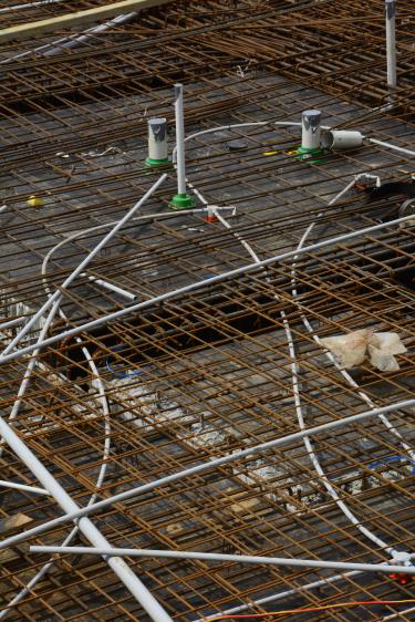
ring
Building services engineering comprisesand plumbing or public health (MEP) engineeh following:
|
|---|
Design management is the business side of design, which aims to create the right environment to control and support a culture of creativity and innovation, and to embrace the iterative nature of design involving the many disciplines that, collectively, will deliver design solutions – and all at the
same time as ensuring that an organisation’s commercial goals and objectives are achieved and that all is done in an ethically sound way.
Project design requirements include:
Supporting documentation includerecords of:
• anchorage requirements for pipes and fittings
• minimum pipe classes and required pipes, fittings and appurtenances
Fire fighting
Fire safety assessments relate mostly to the requirements of professional fire-fighters in the event of a fire and these include:
A sanitary drainage system is designed to collect and carry wastewater or sewage discharge from fixtures within a building to a point of connection with the authority sewer or an on-site treatment plant.
All work must comply with AS 3500 which specifies (amongst other things) the minimum falls and grades for waste pipes.
Table 3.2 in Section 3 of AS/NZS 3500.2:2003 provides advice on the minimum grades for vented and unvented drains. All main drains must be laid at a minimum grade of 1.65%.
|
|---|
A drain of DN 65 must be laid at a minimum grade of 2.50% or a ratio of 1 in 40.
A drain of DN 100 must be laid at a minimum grade of 1.65% or a ratio of 1 in 60.
discharged to an authority's sewer system.
Businesses that produce trade waste may include:
• dentists
• restaurants and cafes
obtain guidelines about the disposal or pre-treatment of trade waste.
Pre-treatment of trade waste
100mm above ground level to prevent the ingress of stormwater.
Arrestors vary in type and size depending on the type of trade waste and the flow rate of the
|
|---|

You can install grease arrestors either above or below ground.
The engineer will want the pipe(s) to pass through the neutral axis. This may not be possible due to the required falls. This may require additional reinforcement and local beam thickening, so it is obvious the structural engineer needs to be involved.
Similarly, sewer pipe penetrations through suspended slabs and beams will require the same attention.
When designing and installing the sewer system it is wise to make allowances for possible future needs such as grease trap connections for the future. It is wise to allocate space for future change of tenant and change of needs. Changing sewer services after the building is complete can be very expensive!
3. What structural considerations will need to be addressed?
4. Where could a grease trap be installed for the café area?

Stormwater
• compliance with local authorities,
• workplace health and safety issues, and,
Unlike sewage, stormwater is generally not treated before being discharged into waterways, wetlands and the sea. So stormwater includes anything the rainwater carries along with it.
Poorly managed stormwater can cause problems, such as erosion, and it can transport litter, sediment and chemical pollution to water catchment areas. On the other hand, stormwater is often wasted when it could be used for recycling purposes.
In urban areas, this is an important source of stormwater and needs to be managed to ensure the run-off goes where it should. Designers will need to be aware of:
|
|---|

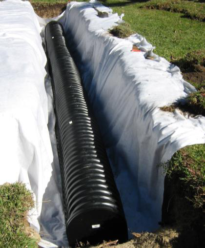

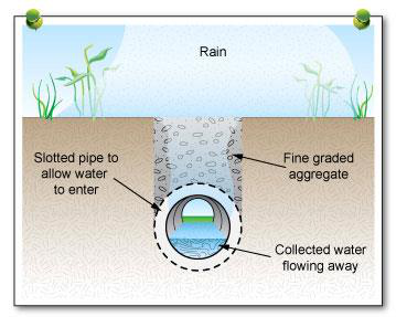


Surface water collected using grated drains
|
|---|
Subsoil drain
Piping for stormwater drains is usually constructed from PVC, reinforced concrete or Fibre Reinforced Cement (FRC).
2. Piping using pumps

3. Open channels
In order to slow the flow of stormwater into water catchments two main techniques are used:
1. On-site stormwater detention

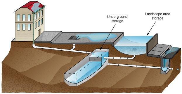
|
|||
|---|---|---|---|
 |
|||

3. Given that all rainwater from the project must be collected and controlled, suggest a suitable method for collecting surface run-off and a pathway for it to the detention tank.
4. Given that the RL of the carpark will be RL 20.300 and the point of discharge street gutter is RL 22.000. Suggest a method of disposing of the detained rainwater collected in the detention tank, which has been located within the building.
|
|---|
All electrical work must comply with AS 3000 Wiring Rules. Some statutory supply authorities may impose particular requirements for their locality.
The occupiers of the building will dictate the electrical needs. It is desirable to have electrical services concealed. To achieve this, it is best practice to consult with the owners and tenants to determine their requirements and design this service into the building.
If this cannot be done then the builder should provide electrical service to hubs within the building and provide metering facilities to a suitable distribution room with appropriate security.
 |
|
|---|
Consult the HIA Student Accommodation Project documentation.
5. Design a suitable electric light layout for the Ground Floor and the ideal switch locations.
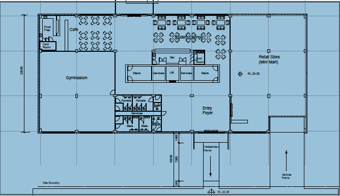
|
|---|
HVAC and also heating, ventilation, and air conditioning) is the tecd veental comfort. Its goal is to provideand acceptable HVAC system design is a sub-discipline of
bales of an is sometimes added to thor HVilating in HACR (such as the designation of HACR-rated.HVAC is important in the design of medium to large industrial ans such as and in marine environments such as where safe ande regulated with respect to temperatidity, using fresrs.
In modern buildings the design, installation, andof these functions are integrated into one or more HVAC systems. For very smallctors normally estimate the capacity, engineer, and select HVAC systems and equipment. For larger buildings, building service designers, mechanical engineers, orengineers analyze, design, and specify the HVAC systems. Specialty mechanic fabricate and commission the systems. Building permits and code-compliance inspections of the installations are normally required for all sizes of building.
District networks

Heaters are appliances whose purpose is to generate heat (i.e. warmth) for the building. This can be done via Such a system contains a orto heat water, steam, or aiation such as ar ain a large building. The heat can be transferred or
is the ventilation of a building with outside air without using fans or other s. It can be via operable windows, louvers, orwhen spaces are small and the architecture permits. In more complex schemes, wwed to rise and flow out high building openings to the outside , causing cool outside air to be drawn into low building openings. Natural ventilation n use very little energy, but care must be taken to ensure comfort. In warm or humid climates, maintainingsolely via natural ventilation may not be possible.systems are useups or
supplements. Air-sideside air to condition spaces, but do so using fans, ducts, dampers, and cs to introduce and distribute cool outdoor air when appropriate.An important component of natural ventilation is air change rate or the hourly rate of ventilation divided by the volume of the space. For examplehour means an amount of new air, equal to the volume of the space, is added every ten minutes. For human comfort, a minimum of four air changes per hour is typical, though warehouses might have only two. Too high of an air change rate may be uncomfortable, akin to awhich have thousands of changes per hour. The highest air change rates are for cro, bars, night clubs, commercial kitchens at around 30 to 50 air changes per hour.
An air conditioning system, or a standalone air conditioner, provides cooling andfor all or part of a building. Air conditioned buildings often have sealed windows, windows would work against the system intended to maintain constant indoor air conditions.
|
|---|
An alternative to central systems is the use of separate indoor and outdoor coils in split systems. These systems, although most often seen in residential applications, are gaining popularity in small commercial buildings. The evaporator coil is connected to a remote condenser unit using
refrigerant piping between an indoor and outdoor unit instead of ducting air directly from the outdoor unit. Indoor units with directional vents mount onto walls, suspended from ceilings, or fit into the ceiling. Other indoor units mount inside the ceiling cavity, so that short lengths of duct handle air from the indoor unit to vents or diffusers around the rooms.
All modern air conditioning systems, even small window package units, are equipped with internal air filters. These are generally of a lightweight gauzy material, and must be replaced or washed as conditions require. For example, a building in a high dust environment, or a home with furry pets, will need to have the filters changed more often than buildings without these dirt loads. Failure to replace these filters as needed will contribute to a lower heat exchange rate, resulting in wasted energy, shortened equipment life, and higher energy bills; low air flow can result in "iced-up" or "iced-over" evaporator coils, which can completely stop air flow. Additionally, very dirty or plugged filters can cause overheating during a heating cycle, and can result in damage to the system or even fire.
Because an air conditioner moves heat between the indoor coil and the outdoor coil, both must be kept clean. This means that, in addition to replacing the air filter at the evaporator coil, it is also necessary to regularly clean the condenser coil. Failure to keep the condenser clean will eventually result in harm to the compressor, because the condenser coil is responsible for discharging both the indoor heat (as picked up by the evaporator) and the heat generated by the electric motor driving the compressor.
|
||
|---|---|---|

|
|||
|---|---|---|---|
Consult the HIA Student Accommodation Project documentation.
What are the air-conditioning requirements for the Project as distinct from ventilation?
Gas service
Polyethylene (PE), nylon, black steel, galvanised steel and copper are just some of the piping materials approved for use in gas installations by plumbers. Other types of materials include uPVC, composite and stainless steel.
Copper is the most commonly specified material used today. However, your choice of material should be based not only on the job specifications, but also on its cost effectiveness and suitability for the job and pipe materials compliance with regulations specified in AS 5601.
|
|
|---|
Contractors should check the Table 3.2 and Section 5 of AS 5601 for more information on flue materials and their use in the construction of an appliance flue system.
• conduct a site inspection to determine the site conditions
• meet the job specifications
This process will ensure that the gas supply levels will be sufficient for the Project’s requirements.
Expected tenant needs should be considered and perhaps a certain amount of ‘fat’ should be included.
|
|---|

Contractors must also plan how they will manage the protection of the environment from the potential impacts of any work they do. As part of their planning process practitioners will need to undertake a hazard and risk assessment of each site they are working on and document how they plan to manage the risks (a SWMS).
The hazards that may affect sites where builders are planning to design a consumer gas installation include:
• tools, plant and equipment
|
|
|---|
resistant levels (FRL’s) are such as slabs and masonry walls are structural elements and designed both for their structural adequacy and their ability to provide save levels of fire resistance. These materials are discussed earlier and in the Building Codes course.
Telecommunications and Alarms
As already discussed, tenant requirement will determine the services required. It is very important to have as much information at the planning stage so that any structural considerations are available and can be built into the structure.
If insufficient information is available, the Builder can only make an educated guess or must rely on the design to make all allowances required.
|
|---|
The pathways for the building’s expected services must be planned into the structural elements and allowances made. The structure may need to be altered to accommodate these building elements so there is a simple “fit” between the required services and the building’s structure. Falls, compliant with Australian Standards, for services such as drainage will need to factored into suitable pathways such as ceilings and service shafts. Similarly, air-conditioning and ventilation requirements will have to be planned for.