
Drilling Engineering Assignment Papers
HERIOT-WATT UNIVERSITY
DEPARTMENT OF PETROLEUM ENGINEERING
Examination for the Degree of MEng in Petroleum Engineering
Drilling Engineering
Section A
A1
- List and describe the function of each of the component parts of the hoisting system on a conventional land drilling
[5]
- Calculate the tension on the fast line and the dead line and the vertical load on the derrick when the following drillstring is pulled from the
Buoyant weight of string 150,000 lbs
Weight of travelling Block and hook 10,000 lbs Number of Lines strung between crown and
travelling block 8
Efficiency of sheave system 81.4%
[3]
A2
- Describe three reasons for using Drillcollars in the drillstring
[5]
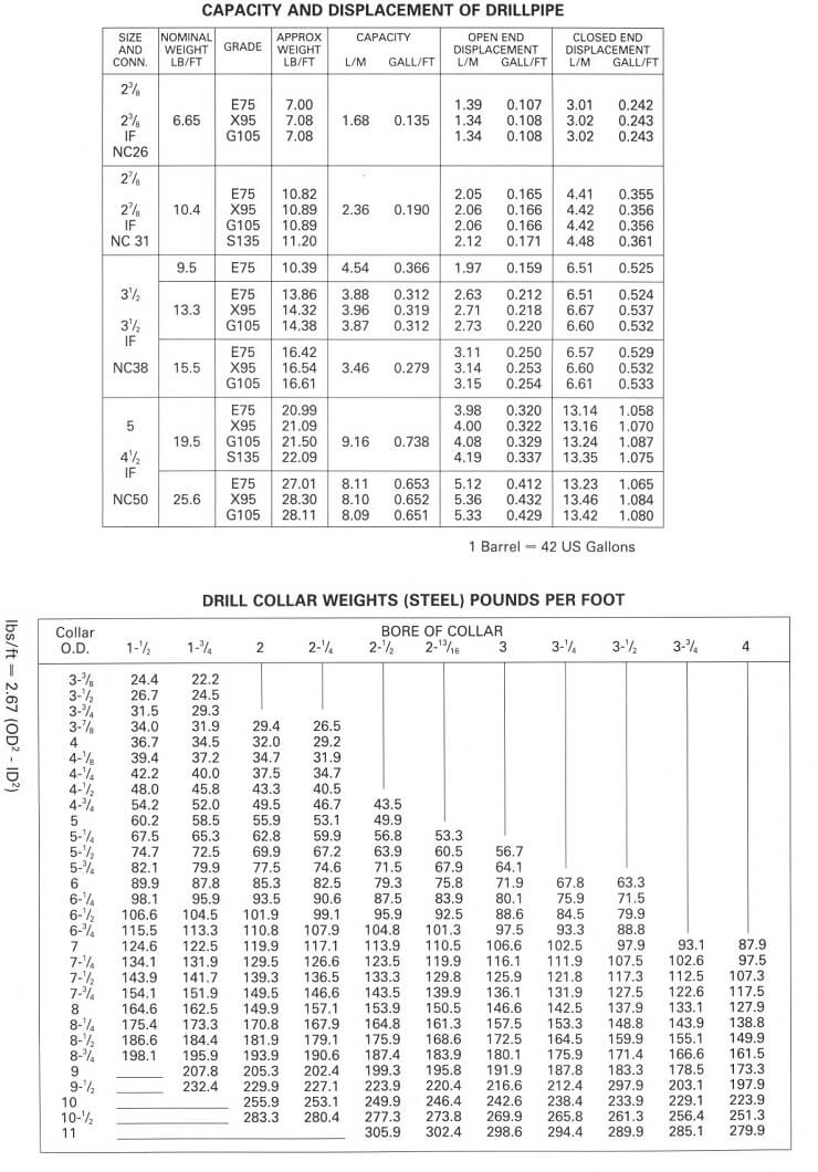
- Calculate, using the tables provided in Attachment 1, the length of 9 1/2” x 2 13/ 16” drillcollars that would be required to ensure that the entire length of the following drillpipe string is in tension in 12 ppg mud:
8000 ft of 5” 19.5 lb/ft Grade G drillpipe with 4 1/2” IF connections.
[3]
A3
- Describe the mechanisms which result in an improvement in the “drillability” of an overpressured formation and which should be considered when calculating the “d”
[4]
- List and describe three other indicators, other than the “d” exponent, which might suggest that an overpressured shale had been
[4]
A4
- A milled tooth roller cone drillbit is pulled from the borehole and graded with the following grading (the IADC dull grading system is given in Attachment 2).
4 4 BT A F 1/8 PB PR
Discuss your interpretation of this grading and what features you would suggest should be considered in selecting the next bit to be run in the well.
[3]
- Calculate the cost per foot of the bit run on the basis of the following information:
|
COST |
DEPTH IN |
DEPTH OUT |
TIME ON BOTTOM |
|
(£) |
(FT.) |
(FT.) |
(HR.) |
3500 7100 7306 14.9
Assuming:
Trip Time = 8 hrs
Rig rate = £48000/day.
[2]
- In what ways is the cost per foot equation used when planning the well and during the well drilling operation
[3]
A5
- List the steps in the procedure for conducting a leak off
[2]
- The results from a Leak off test which has been conducted below the 9 5/8” casing shoe of a well are presented Calculate the maximum allowable mudweight which can be used in the hole section below the 9 5/8” casing shoe:
|
TVD of 9 5/8" Shoe : Mudweight in hole : Vol. pumped bbls |
6500 ft. 10 ppg Surface Pressure psi | |
|
0.5 |
30 | |
|
1.0 |
110 | |
|
1.5 |
205 | |
|
2.0 |
295 | |
|
2.5 |
390 | |
|
3.0 |
475 | |
|
3.5 |
570 | |
|
4.0 |
655 | |
|
4.5 |
760 | |
|
5.0 |
800 | |
|
5.25 |
820 |
[4] |
- Calculate the MAASP for the subsequent hole section when the mud weight is 11
[2]
A6
- List and briefly describe three of the warning signs that a driller should see if a gas influx had occurred
[4]
- Describe the operations which must be undertaken when a kick is detected whilst drilling.
[3]
- In the case of a gas influx, why must the well killing operation be started as soon as possible? [1]
Section B
B7 For a given depth, well orientation and rock type, it is usually possible to select a mud weight which is appropriate from a rock mechanics point of view, i.e. wellbore failure is prevented. Explain why this is possible, addressing all types of wellbore failure in your answer.
[8]
B8 Tests conducted on a rock type gave the following data:
Triaxial factor 2.8
In situ strength enhancement 0.10MPa In situ unconfined compressive strength 4MPa
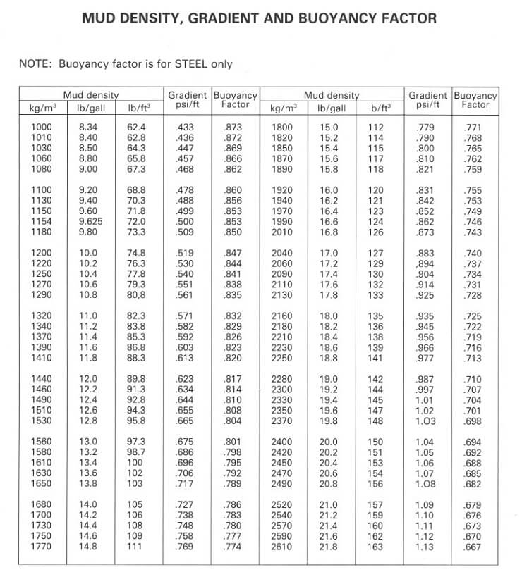
Determine the minimum mud weight required to prevent wellbore failure in this rock while drilling through it at 5000m depth with a vertical well, where the pore pressure is 60MPa and the stress ratio is 0.85. A data sheet (Attachment 5) is provided.
[8]
Section C
C9
- Describe the main factors which influence the pressure loss when circulating fluid through the drillstring and annulus when drilling?
[6]
- How is the onset of turbulence identified when using non-Newtonian drilling fluids in annuli?
[4]
- Select the optimum flowrate and nozzle sizes for the next bit run if prior to pulling a dulled bit from the hole the pressure losses in the circulation system are calculated to be as follows :
|
Flowrate GPM |
Ptotal psi |
Pbit psi |
Pcirc. psi |
|
860 |
4400 |
2400 |
2000 |
|
680 |
2890 |
1590 |
1300 |
|
500 |
1650 |
910 |
740 |
|
350 |
845 |
465 |
380 |
Density of Drilling Fluid = 0.65 psi/ft. Maximum Pumping Pressure = 4700 psi
Note: i. Use the attached log-log paper and Table 1 and 2 (Attachment 3)
- Nozzle Area =
[7]
- Describe the way in which the pressure losses in the system change as the hole section is deepened and how this affects the optimisation of the hydraulics of the system.
[3]
C10
- State the principal functions of the following casing strings:
conductor; surface; intermediate; and production casing.
[8]
- Calculate the burst and collapse loading which will be used in the selection of casing for the following production casing string:
Top of Production Packer : 7200 ft
Formation Fluid Density : 9 ppg
Expected gas gradient : 0.115 psi/ft Depth of Production Interval (TVD) : 7350-7750ft Max. expected pressure in production intervals : 3700 psi Packer fluid density : 9 ppg
Design Factors (burst) : 1.1 (collapse) : 1.0
Note : Gaslift may be used at a later stage in the life of this well.
[10]
- Describe the effect of tensile loading on the burst and collapse rating of casing?
[2]
C11
- Describe, with the aid of diagrams, the Tangential and Balanced tangential mathematical models used to describe and calculate the trajectory of a
[5]
- What are the sources of error when determining the position of the
[3]
- Whilst drilling a deviated well to a target at 11000 TVD. The following data is recorded at station No. 37 (The target bearing is 132o)
|
STATION |
MD |
INC. |
AZI. |
N |
E |
TVD |
VS |
|
36 |
8400 |
35 |
124 |
-328 |
1044 |
7900 |
1005 |
|
37 |
8600 |
38 |
125 |
Calculate the North and East co-ordinates, TVD and vertical section of station No. 37 using the average angle method.
[12]
C12 The 13 3/8” intermediate casing string of a well is to be cemented in place with a two stage cement job. The details of the job are as follows :
Previous Casing Shoe (20") : 1800 ft
13 3/8" 72 lb/ft Casing Setting Depth : 5100 ft 17 1/2" open hole Depth (Calipered @ 18" average) : 5130 ft Multi-Stage Collar Depth : 1750 ft
Shoetrack : 60 ft
Cement stage 1 (5100-3300 ft.)
Class ‘G’ + 0.2% D13R (retarder) : 15.8 ppg
Yield of Class ‘G’ + 0.2% D13R : 1.15 ft3/sk
Mixwater Requirements : 0.67 ft3/sk
Cement stage 2 (1750-1250 ft.)
Class ‘G’ + 8% bentonite + 0.1% D13R : 13.2 ppg Yield of Class ‘G’ + 8% bentonite + 0.1% D13R : 1.89 ft3/sk Mixwater Requirements : 1.37 ft3/sk
- Calculate the following (See Attachment 4 for capacities):
- The required number of sacks of cement for the 1st stage and 2nd stage of the job (Allow 20% excess in open hole).
- The volume of mixwater required for each
- The displacement volume for each
[10]
- Calculate the static bottomhole pressures generated during the above cementing operations.
[2]
- Would the above pressure accurately represent the pressures on the bottom of the well when the cementing operation is being conducted?
[2]
- Prepare a program for a two stage cementing operation and describe the ways in which a good cement bond can be
[6]
|
n |
2.0 1.9 1.8 1.7 1.6 1.5 1.4 1.3 1.2 1.1 |
1.0 |
|
W IF |
0.50 0.51 0.53 0.54 0.56 0.57 0.59 0.61 0.60 0.65 |
0.67 |
W HHP 0.33 0.34 0.36 0.37 0.38 0.40 0.42 0.43 0.45 0.48 0.50
|
NOZZLE SIZE |
NOZZLE AREA (in.2) |
|
18-18-18 |
0.75 |
|
18-19-17 |
0.72 |
|
18-17-17 |
0.69 |
|
17-17-17 |
0.67 |
|
17-17-16 |
0.64 |
|
17-16-16 |
0.61 |
|
16-16-16 |
0.59 |
|
16-16-15 |
0.57 |
|
16-15-15 |
0.54 |
|
15-15-15 |
0.52 |
|
15-15-14 |
0.50 |
|
15-14-14 |
0.47 |
|
14-14-14 |
0.45 |
|
14-14-13 |
0.43 |
|
14-13-13 |
0.41 |
|
13-13-13 |
0.39 |
|
13-13-12 |
0.37 |
|
13-12-12 |
0.35 |
|
12-12-12 |
0.33 |
|
12-12-11 |
0.31 |
|
12-11-11 |
0.30 |
|
11-11-11 |
0.28 |
|
11-11-10 |
0.26 |
|
11-10-10 |
0.25 |
|
10-10-10 |
0.23 |
|
10-10-9 |
0.22 |
|
10-9-9 |
0.20 |
|
9-9-9 |
0.19 |
|
9-9-8 |
0.17 |
|
9-8-8 |
0.16 |
Attachment 4
VOLUMETRIC CAPACITIES
|
bbls/ft Casing |
ft3/ft |
|
13 3/8” 72 lb/ft Casing: 0.1480 |
0.8314 |
|
Open Hole | |
|
18" Hole 0.3147 |
1.7671 |
|
Annular Spaces | |
|
20” Casing x 13 3/8" Casing 0.1815 |
1.0190 |
|
18” Hole x 13 3/8” Casing 0.1410 |
0.7914 |
Attachment 5
The Adaptation of Wilson’s Equations to Wellbore Stability Prediction
Wilsons’s equations have been adapted to the prediction of wellbore stability by allowing for:
- Pore pressure within the host rock (via concept of effective stress)
- The orientation of the wellbore at some angle other than 90º to the horizontal stresses, i.e. hole deviation from 0 to 90º
- Non-hydrostatic stress fields
Thus for a vertical well, the radius to the outer limit of the yield zone is given by the equation below.
The equation predicting the yield zone radius in a thick production zone is:
re = ì2q - so + p' (k + 1) ü 1
a í (p + p' )(k + 1) ý k - 1
|
Where | ||
|
re |
= |
Radius to outer limit of yield zone |
|
a |
= |
Radius of borehole |
|
k |
= |
Triaxial factor for rock |
= ì1 + sin fü
í ý, f being the angle of internal friction for the rock
î1 - sin fþ
|
so |
= |
In situ unconformed compressive strength |
|
p |
= = |
Effective stress applied to the sides of the wellbore Mud pressure - pore pressure |
p' =
s' o
k - 1
, s' o
beingfound from theequations'1
= s' o
+ks' 3
for broken rock in the yield zone
= 0.1 mPa or 15 psi typically for soft rock
q = Effective hydrostatic stress remote from the opening
= (overburden stress x stress ratio) - pore pressure
Course:- 28-137 Class:- 289DE3
HERIOT-WATT UNIVERSITY
DEPARTMENT OF PETROLEUM ENGINEERING
Examination for the Degree of
MSc/Diploma Distance Learning course in Petroleum Engineering
Drilling Engineering
Monday 10th January 2000 09.30 - 12.30
NOTES FOR CANDIDATES
- This is a Closed Book
- 15 minutes reading time is provided from 09.15 - 30.
- Examination Papers will be marked See separate instructions for completion of Script Book front covers and attachment of loose pages. Do not write your name on any loose pages which are submitted as part of your answer.
- This Paper consists of 2 Sections:- A and
|
5. |
Section A:- Section B:- |
Attempt 5 numbered Questions Attempt 3 numbered Question |
|
6. |
Section A:- Section B:- |
40% of marks [8% per Question] 60% of marks |
Marks for Question parts are indicated in brackets
- This Examination represents 100% of the Class assessment.
8 State clearly any assumptions used and intermediate calculations made in numerical questions. No marks can be given for an incorrect answer if the method of calculation is not presented.
- Answers must be written in separate, coloured books as follows:- Section A:- Blue
Section B:- Green
Section A
A1
- List and briefly discuss three functions of the drill collars used in the BHA of drillstrings.
[3]
- List and describe the function of two other components (other than drillcollars) of the
[5]
A2
- List and discuss three elements of the design of a PDC bit which would be suitable for a soft claystone
[3]
- Briefly describe the structure and content of the IADC dull grading
[5]
3
- a) List and discuss the major considerations when selecting/designing a drilling fluid for a particular
[5]
(b) What are the advantages and disadvantages of oil based mud as opposed to water based mud?
[3]
A4
- Discuss the reasons for conducting a leakoff test when drilling out of a casing shoe.
[2]
- List and describe the procedure for conducting such a test and the calculations that are conducted when the results are
[6]
A5
- Draw and annotate the shear stress Shear rate diagram for a: Power law and; Bingham Plastic Drilling Fluid.
[3]
- Write the mathematical model for each of the models discussed
[2]
- Draw the friction factor Reynolds number relationship for a Power law Fluid and show the impact of the non-Newtonian index on the relationship.
[4]
A6
- List and describe the surface and subsurface components of an MWD
[6]
- Describe two of the modes of data transmission used in mud pulse telemetry systems.
[2]
A7
(a) A typical casing string may be described by the following terms: 9 5/8” 47 lb/ft L-80 VAM
Explain the meaning of each of the terms in this description. Use examples of alternatives to highlight the attributes of this particular casing.
[8]
A8
- List and discuss the constraints on the trajectory of a wellbore which must be considered when designing the wellpath of a deviated
[3]
- Given that the rig position and target location are often fixed, what control does the engineer exercise when designing the geometry of the Discuss the practical/operational limitations on the geometry of the wellpath?
[5]
Section B
B9 The intermediate casing of a development well is to be cemented in place using a two stage cement job.
|
13 3/8” Setting Depth |
: 5900 ft. |
|
17 W” Hole (Calipered to 18”) |
: 5930 ft |
|
Previous Shoe Depth (20”) |
: 1500 ft. |
|
Formation Fluid Density |
: 9 ppg |
|
Shoetrack |
: 60 ft |
|
Cement stage 1 (5930-4500 ft.) | |
|
Class ‘G’ + 0.2% D13R (retarder) |
: 15.8 ppg |
|
Yield of Class ‘G’ + 0.2% D13R |
: 1.15 ft3/sk |
|
Mixwater Requirements |
: 0.67 ft3/sk |
|
Cement stage 2 (1500-1000 ft.) | |
|
Class ‘G’ + 8% bentonite + 0.1% D13R |
: 13.2 ppg |
|
Yield of Class ‘G’ + 8% bentonite + 0.1% D13R |
: 1.89 ft3/sk |
|
Mixwater Requirements |
: 1.37 ft3/sk |
- Calculate the following (See Attachment 1 for capacities):
- The required number of sacks of cement for the 1st stage and 2nd stage of the job (Allow 10% excess over caliper in open hole).
- The volume of mixwater required for each
- The displacement volume for each
[12]
- List and discuss three properties of cement which would be specified when designing the cementation
[6]
- Discuss the possible reasons why a two stage cementation job was programmed for this
[2]
B10 Whilst drilling the 12 1/4" hole section of a vertical well with a mudweight of 11 ppg the driller detects a kick. The well is shut in and the following information is gathered
Surface Readings :
Shut in Drillpipe Pressure : 700 psi
Shut in Annulus Pressure : 900 psi
Pit Gain : 29 bbls
Hole / Drillstring Data :
Hole Size : 12 1/4 “
Depth of kick : 6500 ft.
Previous Casing Shoe : 13 3/8", 54.5 lb/ft
Depth 13 3/8" shoe : 3500 ft. TVD
BHA : Bit : 12 1/4"
Drillcollars : 500 ft of 9" x 2 13/16"
Drillpipe : 5", 19.5 lb/ft
- Calculate and discuss the following :
- The type of fluid that has entered the wellbore ?
- The mudweight required to kill the
- The volume of kill mud that would be required to kill the
[10]
- Briefly explain how and why the wellbore pressure is monitored and controlled throughout the well killing operation (assuming that the ‘one circulation method’ is to be used).
[6]
- Briefly explain why the ‘one circulation method’ is considered to be safer than the drillers method for killing a
[4]
B11 The 9 5/8" production casing string of a well is to be designed for burst and collapse on the basis of the following data.
Setting Depth of 9 5/8" Casing : 8320 ft
Top of Production Packer : 7500 ft
Formation Fluid Density : 9 ppg
Expected gas gradient : 0.115 psi/ft
Depth of Production Interval (TVD) : 7750 - 8220 ft Maximum expected pressure in production
intervals : 4650 psi
Packer fluid density : 9 ppg
Design Factors (burst) : 1.1
(collapse) : 1.1
Casing Available (See Attachment 2 for specifications of this casing):
9 5/8" 47 lb/ft P-110 VAM
9 5/8" 53.5 lb/ft P - 110 VAM
Note :
- Only one weight and grade of casing is to be used in the string
- Design the casing for Burst and Collapse loads (do not consider the tensile loads). Discuss critically the scenarios considered when determining the loading conditions used in the above design
[8]
- List and describe four (4) of the tensile loads which would be considered when designing the casing for
[6]
- List and discuss the operations involved in running casing, from the point at which it arrives on the rig, to the point at which the cementing operation is about to
[6]
B12 It has been decided to drill a deviated well to a target at 8700 ft. TVD. The well is to be kicked off just below the 13 3/8" casing at 2000 ft. The well is to have a build and hold profile. The details of the well profile are as follows :
KOP : 2000 ft.
Target Depth (TVD) : 8700 ft.
Horizontal Departure of Target : 3200 ft.
Buildup Rate : 2o/100ft
- Calculate the Following :
- The drift angle of the
- The along hole depth at the end of the build up (iii)The along hole depth at the target.
[12]
- List and discuss the advantages and disadvantages of the various types of surveying systems that could be used to survey this well whilst
[4]
- List and discuss two types of tool or techniques that could be used to alter the
direction of this well if it were found to be deviating from the designed course.
[4]
End of Paper
Attachment I
VOLUMETRIC CAPACITIES
|
Drillpipe |
bbls/ft |
ft3/ft |
|
5" drillpipe : |
0.01776 |
0.0997 |
|
Drillcollars 9" x 2 13/16" Drill collar: |
0.0077 |
0.0431 |
|
Casing | ||
|
13 3/8" 72 lb/ft Casing: |
0.1480 |
0.8314 |
|
Open Hole | ||
|
18" Hole |
0.3147 |
1.7671 |
|
Annular Spaces | ||
|
13 3/8" casing x 5" drillpipe: |
0.1302 |
0.7315 |
|
12 1/4" hole x 5" drillpipe: |
0.1215 |
0.6821 |
|
12 1/4" hole x 9" drillcollars: |
0.0671 |
0.3767 |
|
18" hole x 13 3/8" Casing: |
0.1410 |
0.7914 |
|
20" Casing x 13 3/8" Casing: |
0.1815 |
1.0190 |
Attachment 2
CASING LOAD RATINGS
|
Burst |
Collapse |
Tension |
|
(psi) |
(psi) |
(lbs) |
9 5/8" 47 lb/ft P-110 VAM 9440 5310 1493000
9 5/8" 53.5 lb/ft P - 110 VAM 10900 7930 1710000
