Drilling Engineering Tutorials
Drilling Tutorials 2011
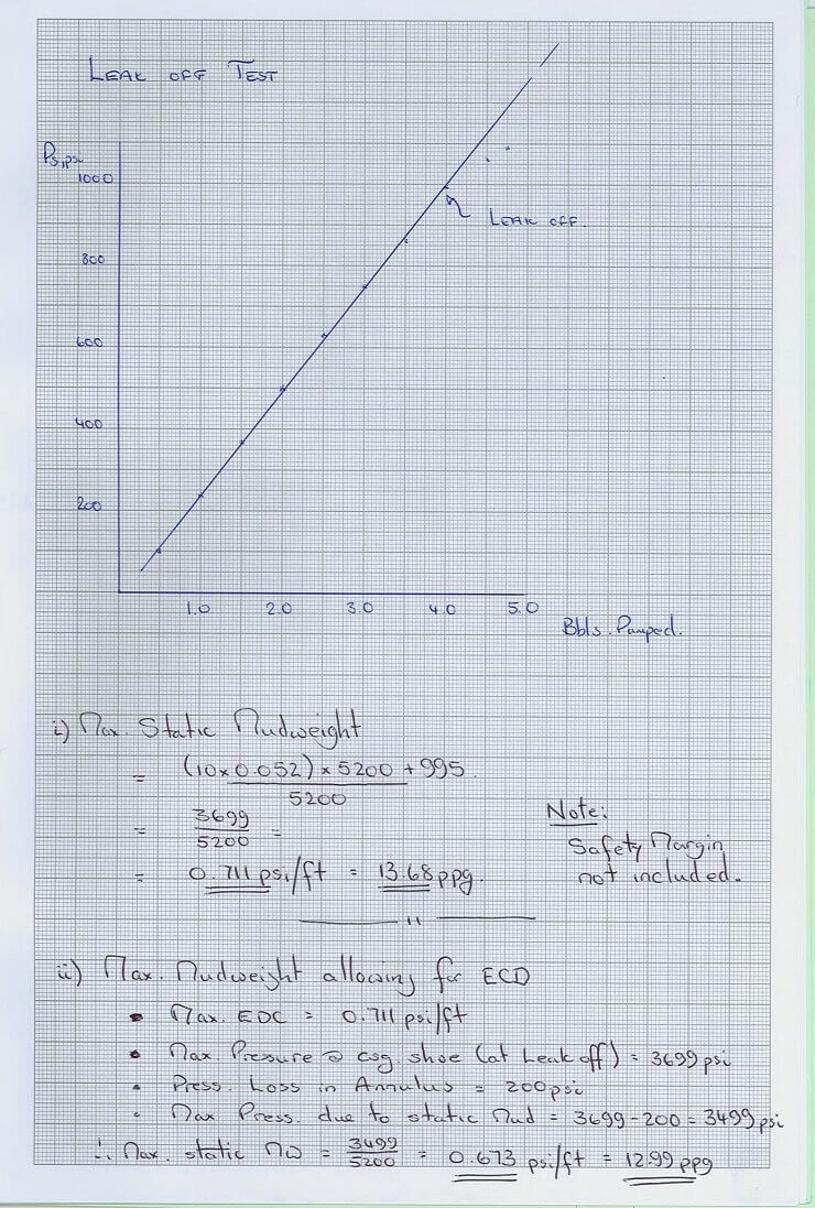
Ex. 1 Leakoff Test
After having conducted a Leak off test at the 13 3/8" casing shoe of a vertical well the following data is reported :
TVD of 13 3/8" Shoe : 5200 ft. Mudweight in hole : 10.0 ppg
|
Vol. pumped bbls |
Surface Pressure psi |
|
0.5 |
100 |
|
1.0 |
240 |
|
1.5 |
370 |
|
2.0 |
500 |
|
2.5 |
630 |
|
3.0 |
750 |
|
3.5 |
860 |
|
4.0 |
995 |
|
4.5 |
1060 |
|
4.75 |
1090 |
- What is the maximum allowable static mudweight in the next (12 1/4") hole section?
- Assuming that the circulating pressure losses in the annulus will be 200psi, what is the maximum allowable mudweight, (allowing for ECD) in the next (12 1/4") hole section?
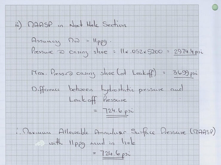
- What would be the MAASP in the next hole section, if the mudweight in the next hole section was increased to 11.0 ppg ?
(State clearly any assumptions in your answer) (6)
Drilling Tutorials 2011
Ex. 2 Well Control
Whilst drilling the 12 1/4" hole section of a vertical well with a mudweight of 10.5 ppg the driller detects a kick. The well is shut in and the following information is gathered
Surface Readings :
Shut in Drillpipe Pressure : 700 psi Shut in Annulus Pressure : 900 psi Pit Gain : 33 bbls
Hole / Drillstring Data :
Hole Size : 12 1/4 "
Depth of kick : 7250 ft. TVD Previous Casing Shoe : 13 3/8", 53.5 lb/ft Depth 13 3/8" shoe : 3800 ft. TVD
LOT at Previous shoe : 3230 psi (0.85 psi/ft Equivalent Mudweight)
BHA : Bit : 12 1/4"
Drillcollars : 400 ft of 9" x 2 13/16"
Drillpipe : 5", 19.5 lb/ft
- Calculate and discuss the following :
- The type of fluid that has entered the wellbore ?
- The mudweight required to kill the
(8)

VOLUMETRIC CAPACITIES
|
Drillpipe |
bbls/ft |
ft3/ft |
|
5" drillpipe : |
0.01776 |
0.0997 |
|
Casing 13 3/8" 72 lb/ft Casing: |
0.1480 |
0.8314 |
|
Open Hole 13" Hole |
0.1642 |
0.9220 |
|
18" Hole |
0.3147 |
1.7671 |
|
Annular Spaces | ||
|
12 ¼" hole x 5" drillpipe |
0.1215 |
0.6822 |
|
12 ¼" hole x 9" drillcollars: |
0.0671 |
0.3767 |
|
13” Hole x 9 5/8" Casing |
0.0742 |
0.4166 |
|
18" hole x 13 3/8" Casing: |
0.1410 |
0.7914 |
|
20" Casing x 13 3/8" Casing: |
0.1815 |
1.0194 |
|
8 1/2" hole x 5" drillpipe: |
0.0459 |
0.2577 |
|
8 1/2" hole x 6 1/4" drillcollars: |
0.0330 |
0.1926 |
Drilling Tutorials 2011
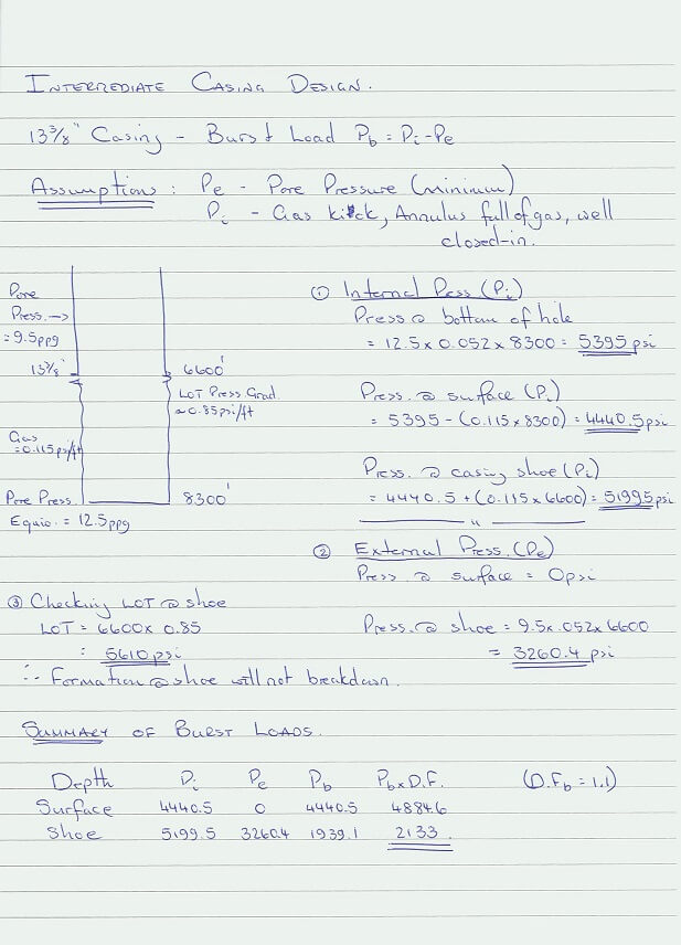
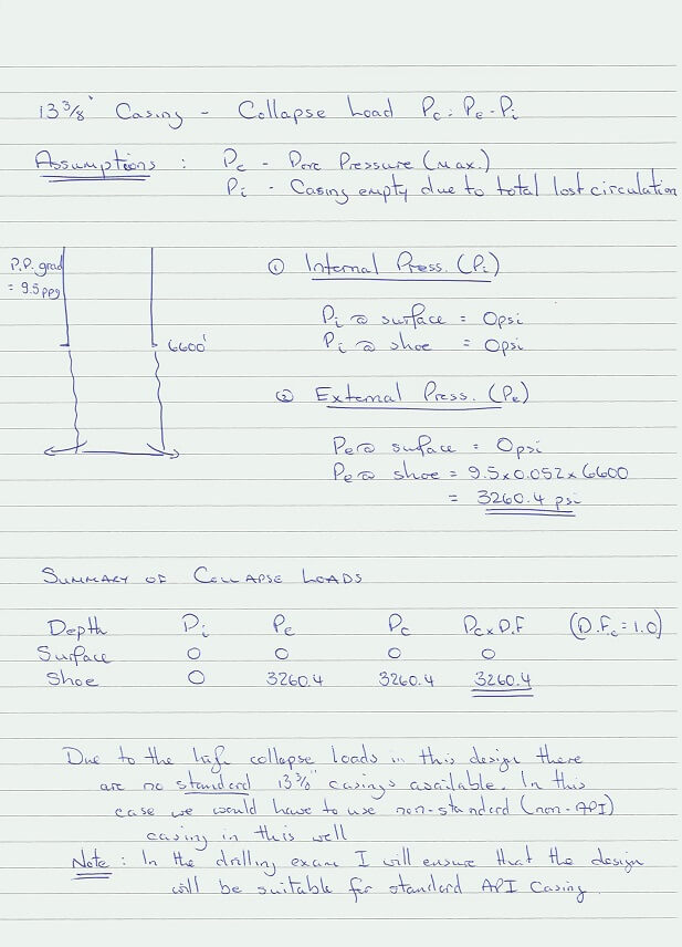
Ex. 3 Intermediate Casing Design
You are required to calculate the burst and collapse loads on the 13 3/8” intermediate casing for a gas development well on the basis of the following data :
|
Casing Size : Setting Depth : Formation Fluid Density : |
13 3/8" 6600 ft 9.5 ppg | |
|
Mud weight in which the casing is to be run : Depth of next (12 1/4”) hole section : Expected Pore Pressure Gradient at |
11.5 ppg 8300 ft | |
|
bottom of 12 1/4” hole: |
12.5 ppg | |
|
Expected Frac. Pressure Gradient at the 13 3/8” shoe Expected gas gradient : |
0.85 psi/ft. 0.115 psi/ft | |
|
Design Factors : (Burst) |
1.1 | |
|
(Collapse) |
1.0 |
Drilling Tutorials 2011
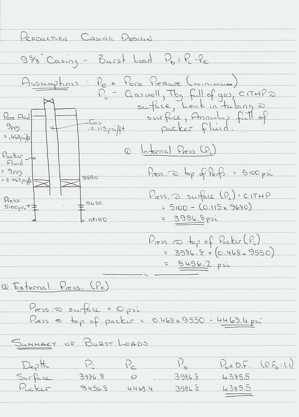
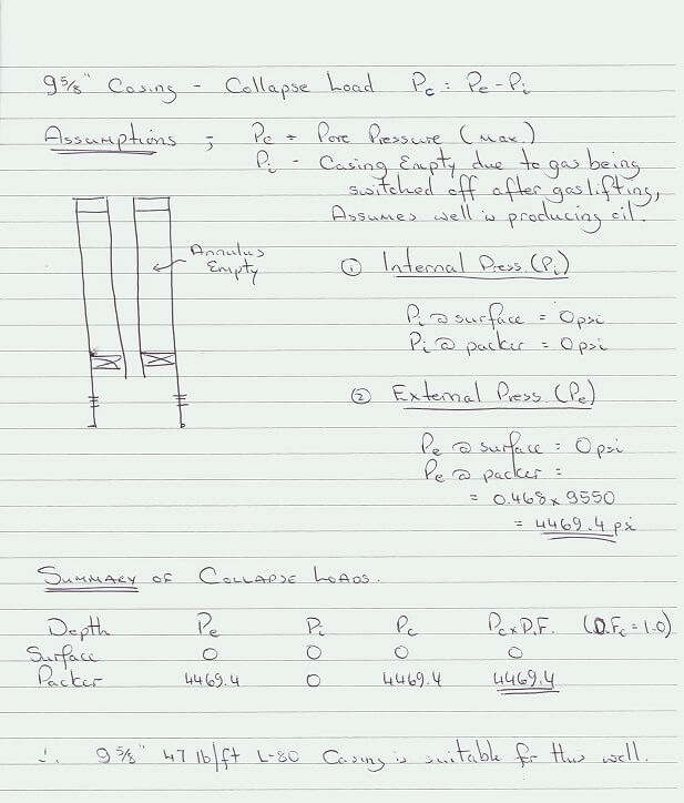
Ex. 4 Production Casing Design
You are required to calculate the burst and collapse loads on the 9 5/8" production casing string for a gas development well on the basis of the following data :
|
Setting Depth of 9 5/8" Casing : Top of Production Packer : Formation Fluid Density : Expected gas gradient : |
10100 ft 9550 ft 9 ppg 0.115 psi/ft |
|
Depth of Production Interval (TVD) : |
9680 - 9950 ft |
|
Maximum expected pressure at top of Perforations : |
5100 psi |
|
Packer fluid density : |
9 ppg |
|
Design Factors (burst) : |
1.1 |
|
(Collapse) : |
1.0 |
Drilling Tutorials 2006
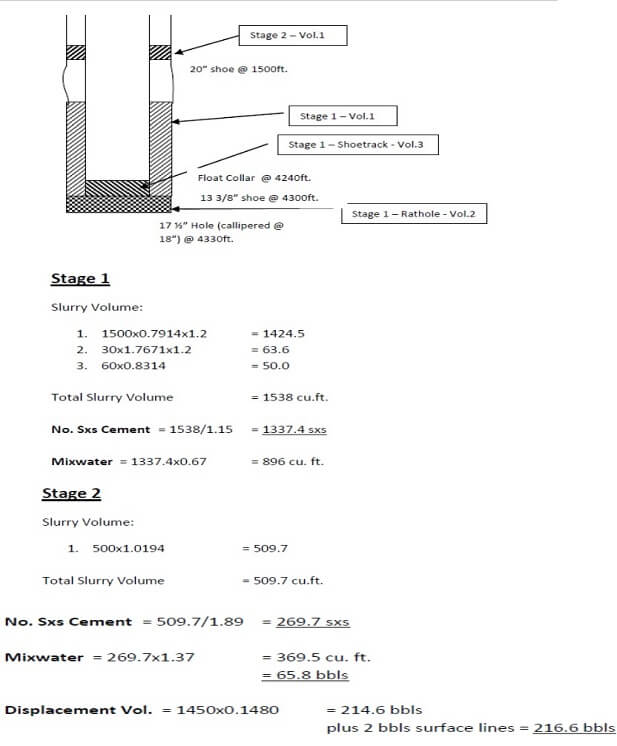
Ex.6 - Cementing
The 13 3/8” intermediate casing string of a well is to be cemented in place with a two stage cement job. The details of the job are as follows :
|
Previous Casing Shoe (20") : |
1500 ft. |
|
13 3/8" 72 lb/ft Casing Setting Depth : |
4300 ft. |
|
17 1/2" open hole Depth (Calipered @ 18" average) : |
4330 ft. |
|
Multi-Stage Collar Depth : |
1450 ft. |
|
Shoetrack : |
60 ft. |
|
Mud Density When cement job starts : |
12 ppg |
Cement stage 1 (4300-2800 ft.)
Class 'G' + 0.2% D13R (retarder) : 15.8 ppg
Yield of Class 'G' + 0.2% D13R : 1.15 ft3/sk
Mixwater Requirements : 0.67 ft3/sk
Cement stage 2 (1450-950 ft.)
Class 'G' + 8% bentonite + 0.1% D13R : 13.2 ppg Yield of Class 'G' + 8% bentonite + 0.1% D13R : 1.89 ft3/sk Mixwater Requirements : 1.37 ft3/sk
- Calculate the following (See Attachment 1 for capacities):
- The required number of sacks of cement for the 1st stage and 2nd stage of the job (Allow 20% excess above calliper in openhole).
- The volume of mixwater required for each
- The displacement volume for each
(12)
VOLUMETRIC CAPACITIES
|
Drillpipe |
bbls/ft |
ft3/ft |
|
5" drillpipe : |
0.01776 |
0.0997 |
|
Casing 13 3/8" 72 lb/ft Casing: |
0.1480 |
0.8314 |
|
Open Hole 13" Hole |
0.1642 |
0.9220 |
|
18" Hole |
0.3147 |
1.7671 |
|
Annular Spaces | ||
|
12 ¼" hole x 5" drillpipe |
0.1215 |
0.6822 |
|
12 ¼" hole x 9" drillcollars: |
0.0671 |
0.3767 |
|
13” Hole x 9 5/8" Casing |
0.0742 |
0.4166 |
|
18" hole x 13 3/8" Casing: |
0.1410 |
0.7914 |
|
20" Casing x 13 3/8" Casing: |
0.1815 |
1.0194 |
|
8 1/2" hole x 5" drillpipe: |
0.0459 |
0.2577 |
|
8 1/2" hole x 6 1/4" drillcollars: |
0.0330 |
0.1926 |
Solution - Cementing Tutorial
Drilling Tutorials 2011
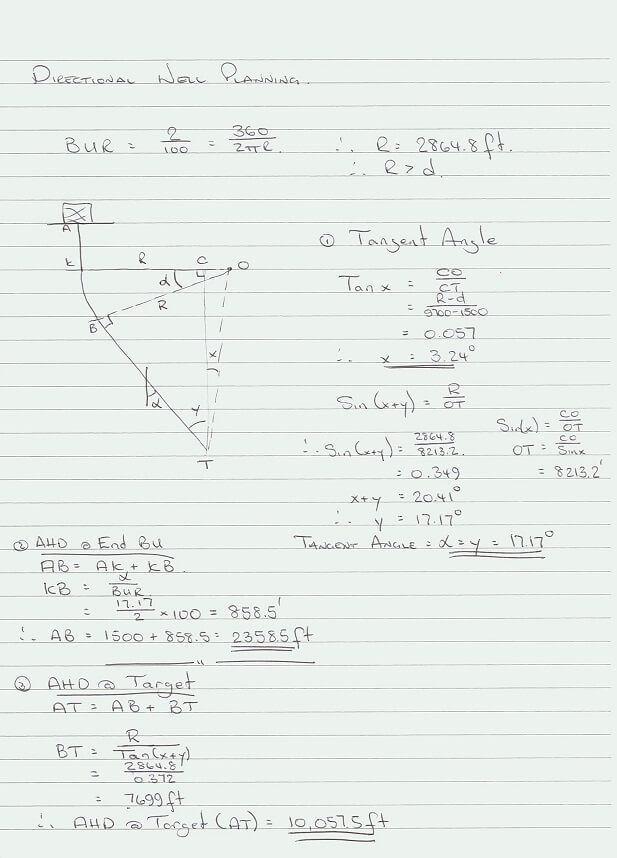
Ex. 5 Directional Well Planning
Using the following data, design a deviated well using a build and hold trajectory.
TVD Target 9700 ft
Horizontal Departure of Target 2400 ft
KOP 1500 ft
BUR 2 degrees/100 ft
Determine the following :
- Tangent
- Along Hole Depth at the end of the Build up Section
- True Vertical Depth and Horizontal departure of End Build up Section
- Along Hole Depth at
Drilling Tutorials 2011
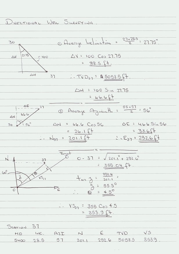
Ex. 6 - Directional Surveying
Whilst drilling a deviated well to a target at 9800 ft. TVD. The following data is recorded at station No. 37 (The target bearing is 60o)
|
STATION |
MD |
INC. |
AZI. |
N |
E |
TVD |
VS |
|
36 |
5300 |
27 |
55 |
175 |
254 |
4970 |
306 |
|
37 |
5400 |
28.5 |
57 |
Calculate the North and East co-ordinates, TVD and vertical section of station No. 37 using the average angle method.