
EGA-222: Electrical Machines Laboratory
EGA-222: Electrical Machines Laboratory
Design and Implementation of a Cascade
Speed-Current Controllers for a Permanent Magnet DC Motor
Learning Outcomes:
- Introduction to model-based simulation approach using MATLAB/Simulink,
- Designing of a Current Controller for a PMDC motor,
- Designing of a Speed Controller for a PMDC motor,
- Simulation and Testing of the Cascade Speed-Current controllers for a PMDC motor.
1 Cascade closed-loop Control of a PMDC Motor
In this section, you will design a cascade control system which has two control loops of motor speed controller and armature current controller. The role of a controller is to generate trigger signals (ie, control voltage) for driving the PMDC motor. A block diagram of the cascade control system is shown in Fig. 1 with an inner current control loop and an outer speed control loop.
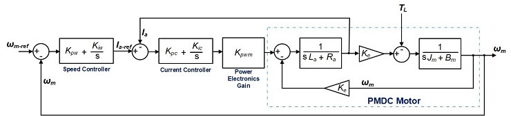
Figure 1: Equivalent Block Diagram of the Cascade Controller for the PMDC Motor
The control system in Fig. 1 consist of the PMDC motor (the plant to be controlled), the gain of the power electronics converter, the speed and current controllers. The speed controller generates the reference current for the current controller. Whereas, the current controller generates the control voltage for driving the PMDC motor.
KeyNote: The parameters of the PMDC motor is the same as in PartA (see the Table in Page 5 of the Pdf “PMDC-PartA”). Note: Km = Ke = Kt
1.1 Task 1:: Design the Current Controller of the PMDC Motor
In this exercise, we will use the famous Proportional Integral (PI) controller to control the armature current of the PMDC motor.
The PI-based current controller of the PMDC motor is given in (1)
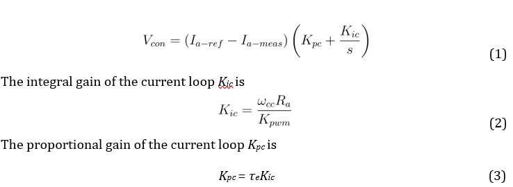
where,
Ia−ref represent the reference armature current from the speed controller, Ia−meas represent the measured armature current from the PMDC motor, ωcc = 2πfcc represent the cut-off frequency of the current control loop in radians/second,
Kpwm = Vin = Va is the power electronics gain, τe is the electrical
time constant of the PMDC motor =,
Vcon is the control voltage output from the current control loop, which is subsequently used to drive the PMDC motor. Note: take fcc = 300 Hz. 1. Complete Table 1.
Table 1: Parameter Selection for the PMDC motor’s Current Controller
|
Parameter |
Symbol |
Value |
Unit |
|
Cut-off frequency of current loop |
ωcc |
rad/s | |
|
Power electronics gain |
Kpwm | ||
|
Armature resistance |
Ra |
Ω | |
|
Armature inductance |
La |
H | |
|
PMDC electrical time constant |
τe | ||
|
Integral gain of current loop |
Kic | ||
|
Proportional gain of current loop |
Kpc |
- Create a new Simulink Model (you can name it as “Design-of-PMDC-Controllers”),
- Use (1) and Table 1 to build the current controller. Hint: Drag and drop the respectively blocks from the Simulink library.
Simulink Library Browser → Continuous → Integrator Limited;
Simulink Library Browser → Discontinuities → Saturation;
- Set the Upper and Lower limits of both the Saturation and Integrator blocks to +1 and -1 respectively,
- Add TWO input ports (In1) and ONE output ports (Out1) to your model, rename the input ports as Ia-ref and Ia-meas; rename the output port as Vcon. Simulink Library Browser → Sources → In1; Simulink Library Browser → Sinks → Out1; See Fig. 2 for reference.
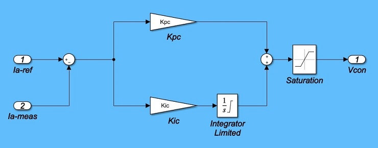
Figure 2: MATLAB Simulink Model of the Current Controller
- Next, create a single module which represents the Current Controller: Click and drag the mouse to highlight all components of the current controller model; right-click on a block within the model and select “Create Subsystem from selection”; rename the new module as “Current-Controller”; and delete the input and output blocks and lines connecting to the module.
See Fig. 3 for reference,
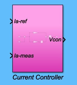
Figure 3: MATLAB Simulink Module of the Current Controller
1.1 Task 2:: Design the Speed Controller of the PMDC Motor
In this section, we will also use the famous Proportional Integral (PI) controller to control the speed of the PMDC motor.
The PI-based speed controller of the PMDC motor is represented in (4)
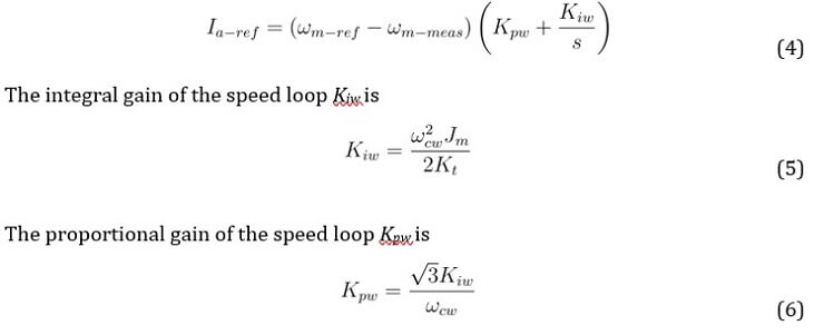
where, ωm−ref represent the reference mechanical speed,
ωm−meas represent the measured mechanical speed from the PMDC motor, ωcw = 2πfcw represent the cut-off frequency of the speed control loop in radians/second,
Jm is PMDC motor’s equivalent moment of inertia,
Kt = Ke is PMDC motor’s torque constant,
Note take: fcw = fcc/10 = 30 Hz.
- Complete Table 2.
Table 2: Parameter Selection for the PMDC motor0s Speed Controller
|
Parameter |
Symbol |
Value |
Unit |
|
Cut-off frequency of current loop |
ωcw |
rad/s | |
|
Moment of inertia |
Jm |
Kg.m2 | |
|
Torque constant |
Kt |
V.s/rad | |
|
Integral gain of speed loop |
Kiw | ||
|
Proportional gain of speed loop |
Kpw |
- Maintain the same Simulink page from Task 1,
- Use (4) and Table 2 to build the speed controller. Hint: Drag and drop the respectively blocks from the Simulink library. See Fig. 4 for reference.
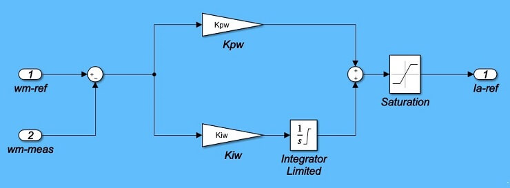
Figure 4: MATLAB Simulink Model of the Speed Controller
Simulink Library Browser → Continuous → Integrator Limited;
Simulink Library Browser → Discontinuities → Saturation;
- Set the Upper and Lower limits of both the Saturation and Integrator blocks to +2.5 and -2.5 respectively,
- Add TWO input ports (In1) and ONE output ports (Out1) to your model, rename the input ports as wm-ref and wm-meas; rename the output port as Ia-ref. Simulink Library Browser → Sources → In1;
Simulink Library Browser → Sinks → Out1;
- Next, create a single module which represents the Speed Controller: Click and drag the mouse to highlight all components of the speed controller model; rightclick on a block within the model and select “Create Subsystem from selection”; rename the new module as “Speed-Controller”; and delete the input and output blocks and lines connecting to the module.
See Fig. 5 for reference,
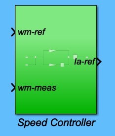
Figure 5: MATLAB Simulink Module of the Speed Controller 13.
Remember to save your work.
1.1 Task 3:: Build the PMDC Motor Model in Simulink
- Open the PMDC Simulink model that you built, for the No-Load test, in PartA (ie, Figure 3 in Page 7),
- Use the Simulink Save As option to make a duplicate copy of your PMDC model,
- Now rearrange the blocks in the new model as shown in Fig. 6 by dragging and moving blocks around,
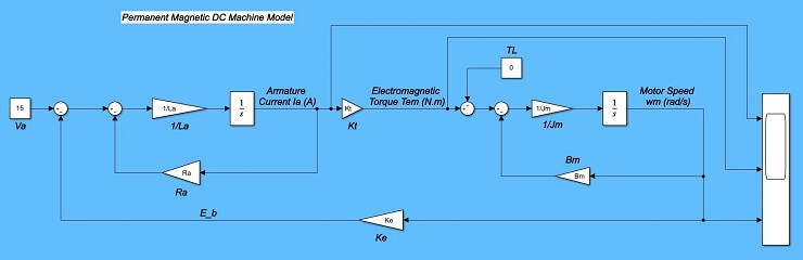
Figure 6: MATLAB Simulink Model of the PMDC Motor
- Run the modified model, and ensure that your results are the same as the Noload test, that was completed in PartA (see Figure 4 in Page 9 of the Document PMDC-PartA),
- Add TWO input ports (In1) and THREE output ports (Out1) to your model, rename the input ports as Va and TL; rename the output ports as Ia, Tem, and wm. Simulink Library Browser → Sources → In1; Simulink Library Browser → Sinks → Out1; See Fig. 7 for reference.
Figure 7: MATLAB Simulink Model of the PMDC Motor
- Next, create a single module which represents the PMDC motor: Click and drag the mouse to highlight all components of the PMDC model; rightclick on a block within the model and select “Create Subsystem from selection”; rename the new module as “PMDC-Motor”; and delete the input and output blocks and lines connecting to the module.
See Fig. 8 for reference,
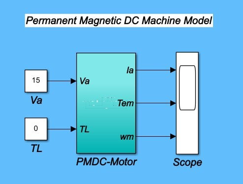
Figure 8: MATLAB Simulink Module of the PMDC Motor
- ReRun the modified model, and ensure that your results are the same as the Noload test, that was completed in PartA (see Figure 4 in Page 9 of the Document
PMDC-PartA),
1.1 Task 4:: Analysis of the PMDC Motor Model with Cascade Closed-loop Control
In this final section, you will use the PMDC Simulink module, and the PI-based speed and current controller (Simulink) modules to build and analyse the cascade control of the PMDC motor.
- Copy the Speed and the Current Controller Modules into the Simulink file entitled PMDC module (from Task 3). See Fig. 9 for reference,
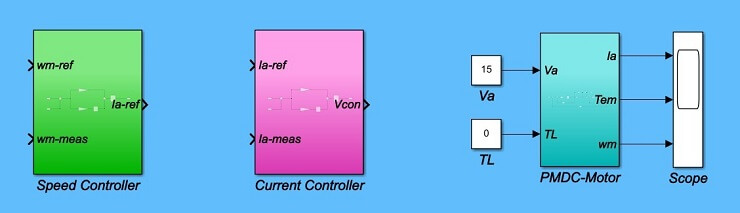
Figure 9: MATLAB Simulink PMDC Module in a Cascade Control System
- Complete the Closed-loop design (See Fig. 1 and Fig. 10 for reference):
- Use the “Constant” block to enter a reference speed (100 rad/s), and a load torque of 0 Nm,
- Use the “Step” block to increase the reference speed by 100 rad/s at t =
1.0sec (Step time = 1, Initial value = 0, Final value = 100), Simulink Library Browser → Sources → Step
- Use the “Mux” block and the Scope to monitor the reference and measured signals of both the motor speed and the armature current, Simulink Library Browser → Signal Routing → Mux
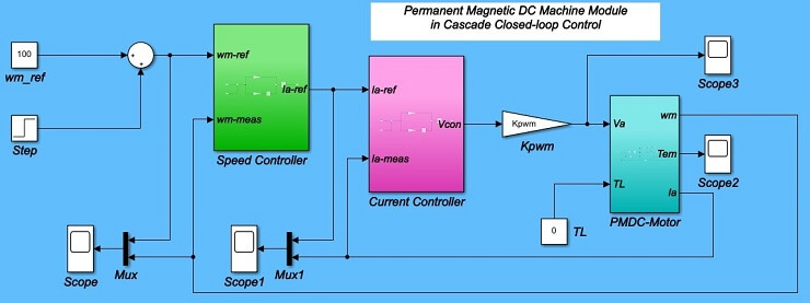
Figure 10: MATLAB Simulink PMDC Module in a Cascade Control System
- Remember to define all relevant variables in your model (refer to Table 1, Table 2, and the Table in Page 5 of the Pdf “PMDC-PartA”),
Use the “Callback” window: Modelling → Model Settings → Model Properties
→ Model Settings → Callbacks → InitFcn*
(See Fig. 11 for reference)
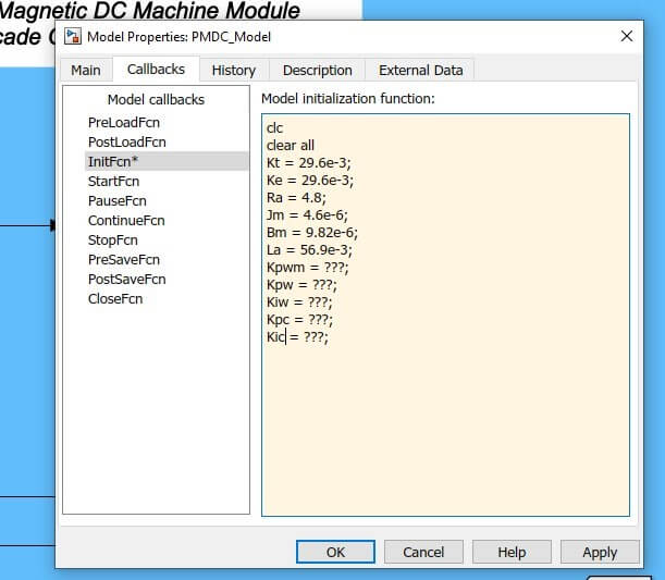
Figure 11: MATLAB Simulink PMDC Module Model Properties
- Change the simulation time to 2-seconds and Run the simulation,
- Record results of the speed and current tracking behaviour, of the cascade control loop, as the reference input speed (wm-ref) varies from 100 rad/s to 200 rad/s with a step time of 1-second. Also, record the result of the motor torque and the armature voltage,
- Save an image of all four scope plots, see sample results in Fig. 12,
- Compare the simulated motor armature current, armature voltage, and electromagnetic torque to the results of the No-load conditions in PartA (in cases where the speeds were near but not exactly equal to 100 and 200 radians/second). Note: If the values don0t match well (say, within 20%), double-check your simulated motor values and double check your controller parameters,
- Note: If your plots are oscillating wildly between large positive and negative values, try reducing the current controller0s proportional constant by a factor of two or more,
- Reflect on all relevant graphs and findings. Try implementing a variable speed reference of 50, 100, 200, 150, and 75 rad/s at a step time of 1, 2, 3, and 4 seconds respectively.
Figure 12: PMDC Motor Speed Reference Tracking
- Use the To Workspace block to send all relevant graphs (responses) to the MATLAB workspace, and write a simple code to plot and format the graphs,
- Repeat the above analysis for load torque TL = 0.04 Nm.
1.5 Discussion
- In the completed PMDC0s speed controller, why is the current controller required?
- Why is there a maximum spike or overshoot in the speed response? can this overshoot be avoided?
- Why do the motor0s torque and current values change significantly when the speed suddenly changes?
- Do you see any effect in the plots of the limits that you set in the controllers? Explain.
- Refer to the step response of the speed controller, and complete Table 3.
Table 3: Step Response Parameter of the Speed Loop
|
Parameter |
Symbol |
Value |
Unit |
|
Percent Overshoot |
%OS |
% | |
|
Peak Time |
Tp |
s | |
|
Settling Time |
Ts |
s | |
|
Steady-state error |
ess |
Peak Value − Desired Value
%OS = × 100 (7)
Desired Value
Tp = is the time required to reach the peak value of the response,
Ts = is the time required for the response to reach and stay within ±2% of the desired value, ess = is the error between the actual output and desired output as time tends to infinity.
- What is the effect of loading (ie TL 6= 0) on the speed, current, torque, and voltage responses?

