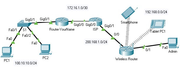
Network Topology
DCOM 218 W01: Cisco II - Final Skills Lab – Summer- Updated

Network Topology
Part 1 – Create the Network and Configure the Interfaces (20 Points)
1. Open Packet Tracer and create a network with the following hardware:
- 2 – 1941 Routers
- 1 – 2960 Switch
- 1 – Home Router (wireless)
- 3 – PCs
- 1 – Tablet PC
- 1 – Smartphone
2. Connect the wired devices with Ethernet cables as shown in the topology.
3. Configure the interfaces and name the switch and routers (display and hostnames) according to the Device Address Table:
|
Device |
Interface |
Address and Prefix |
Default Gateway |
|
Router-YourName |
G0/0 |
172.16.1.1/30 |
n/a |
|
G0/1 |
100.10.10.1/24 |
n/a | |
|
S1 |
VLAN1 |
100.10.10.2/24 |
100.10.10.1 |
|
ISP |
G0/0 |
172.16.1.2/30 |
n/a |
|
G0/1 |
200.168.1.1/24 |
n/a | |
|
PC-1 |
NIC |
DHCP |
DHCP |
|
PC-2 |
NIC |
DHCP |
DHCP |
|
Wireless LAN | |||
|
Home Router (WLAN) |
Internet |
200.168.1.2/24 |
200.168.1.1 |
|
LAN |
192.168.0.1 |
n/a | |
|
Admin |
NIC |
192.168.0.3/24 |
192.168.0.1 |
|
Smartphone |
Wireless |
DHCP |
DHCP |
|
Tablet PC |
Wireless |
DHCP |
DHCP |
Note: If your name is Mary Smith, name your router: Router-Mary, Router-Smith, or Router-MarySmith.
Part 2: Configure Switch Security (25 Points)
Step 1: Configure Fa0/1 and Fa0/2 on S1 with the following:
- Access ports
- Enable port security
- Set the maximum so that only two devices can access each of the two ports
- Secure the ports so that the MAC address of a device is dynamically learned and added to the running configuration
- Set the violation mode so that the ports shut down when the maximum number of secure MAC addresses is exceeded
- Disable all the remaining unused ports
Step 2: Configure Security on S1
Note: Enter the passwords carefully, if the instructor cannot log in with these passwords the student will get a 0 (zero) for this section of the exam.
- Configure CCNA2 as the secret password.
- Configure cisco2 as the console line password and require users to log in.
- Configure cisco2 as the VTY password for lines 0 through 4 and require users to login.
- Encrypt all plaintext passwords.
- Enter the banner Authorized Users Only!
Part 3 – Configure the Routers
Step 1: Configure DHCP on Router-YourName (15 Points)
- Exclude the .1 and .2 addresses from the 10.10.0/24 address range
- Configure the DHCPv4 pool 218-FINAL-POOL for 10.10.0/24 LAN
- Configure the default gateway address
- Include the DNS Server address: 0.0.5
Step 2: Configure IPv4 Static Default Routes (10 Points)
Configure Static Default Routes on each router that will forward packets to the other router.
- On ISP configure a directly connected default static route.
- On Router-YourName configure a next hop static default route.
Save the Running Configuration files for the routers and switch. (5 Points)
Part 4 – Configure a Wireless Network (25 Points)
Step 1: Connect to a Wireless Router (using default IP Address and credentials).
- Ensure that Admin has been configured with correct IP Addressing.
- In the Desktop tab on Admin, choose Web Browser.
- Enter 192.168.0.1in the URL field to open the web configuration page of the wireless router.
- Use admin for both the username and password.
Step 2: Connect the Internet port of the Wireless Router
1. Under the Internet Setup at the top of the Basic Setup page, change the Internet IP address method from Automatic Configuration DHCP to Static IP.
2. Enter the IP address to be assigned to the Internet interface as follows:
- Internet IP Address: 200.168.1.2
- Subnet Mask: 255.255.255.0
- Default Gateway: 200.168.1.1
- DNS Server: 25.0.0.5
3. Under Network Setup for Router IP, ensure the following:
- IP Address:168.0.1
- Subnet Mask:255.255.0
4. Under DHCP Server Settings
- Ensure DHCP is enabled
- Change the following:
The Start IP Address: 192.168.0.50
Maximum number of Users: 10
Static DNS 1: 25.0.0.5
5. Scroll down the page and click Save Settings.
Step 3. Connect the Wireless Clients (Smartphone and Tablet PC)
- Ensure that DHCP is selected under IP Configuration for the two devices.
Part 5: Test your Network – Troubleshoot and verify your implementation by testing the end-to-end connectivity of all devices.
Note: Due to Packet Tracer limitations you will not be able to ping from outside the WLAN to inside. But:
- each device outside the WLAN should be able to ping each other (for example ISP to PC1).
- each device inside the WLAN should be able to ping each other (for example Smartphone to Admin).


