
MSK VS GMSK
1. INTRODUCTION
Memoryless linear modulation schemes such as Phase Shift Keying (PSK-QPSK, OQPSK and DPSK) and Frequency Shift Keying (FSK) possess phase discontinues in the modulated signal which may cause problems for power-efficient and band-limited transmission. To counter the problems, continuous phase modulation schemes are used to allow the application of non-linear power amplifiers with high power-efficiency (Hachmeister et al., 2012). In digital communication, Gaussian Minimum Shift Keying (GMSK) and Minimum-Shift Keying (MSK) modulation schemes are forms of continuous-phase frequency-shift keying (CPFSK). In this report, a comparison is made between MSK and GMSK schemes using measurements of eye diagrams and constellation diagrams for specific signal-to noise-ratio (SNR) and BT product (bandwidth multiplied by time) (Prameela and Pravin, 2015).
2. BACKGROUND THEORY
2.1.Minimum Shift Keying (MSK)
Generally, binary data consists of sharp 0 to 1 and 1 to 0 state transitions which creates extending sidebands (out-of-band signals) in the carrier signal (Sachchidanand Shukla, 2017). The extending sidebands out of the allowable bandwidth creates interference with adjacent channels in many radio communication systems. Minimum shift keying (MSK) is used to reduce the bandwidth significantly to ensure no existence of phase discontinuities (Hachmeister et al., 2012).
The MSK is a form of binary CPFSK with the modulation index . The frequency difference between 0 and 1 states in MSK is always equal to 0.5 of the data rate hence the modulation index is constantly 0.5.
Frequency separation,∆f = f_2 - f1=1/2 T
MSK enables operation of power amplifiers in saturation mode hence making them highly power-efficient and offers higher spectral efficiency in comparison to similar modulation schemes (Sachchidanand Shukla, 2017).
The MSK modulator block diagram is shown in figure 2.1
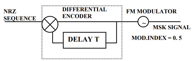
Figure 2.1: MSK modulator block diagram
The MSK modulator encodes each bit in the NRZ sequence as half sinusoids instead of square pulses as in QPSK and OQPSK.
2.1.1. Application of MSK
Due to its features such as compact spectrum, constant envelope and good error performance, MSK modulation is used in most digital communication systems. It is used in micro-satellite communications, deep space communications, navigation and positioning systems, the Blue Ray disc technology and hybrid wireless/optical communication systems (Kamilo Feher, 2015).
2.2.Gaussian Minimum Shift Keying (GMSK)
The GMSK is digital modulation scheme where the modulating signal (information signal) instantaneously varies the phase of the carrier. The GMSK is similar to MSK with the major difference being that GMSK has a pre-modulation Gaussian Filter (Bang and Lee, 2013). The Gaussian filter has a bandwidth defined by its BT product and makes the power output spectrum more compact. The filter has sharp cut-off properties and narrow bandwidth that suppresses the high-frequency components. The time-domain overshoot impulse response of the filter is low for protection against instantaneous deviations. The Gaussian filter’s time-domain impulse response can be described by the following equation.
h(t)=(k1 B)/√π e(k_12 B2 t2 )
where B is the half-power bandwidth and k1=π/√(2 ln2 )
There are several ways of implementing a GMSK modulator. The block diagram of the GMSK modulator is shown in figure 2.2 (Hachmeister et al., 2012)
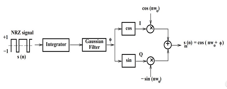
Figure 2.2: GMSK modulation block diagram
In the operation of the GMSK modulator, a Non-Return-to-Zero NRZ (-1,1) sequence is first created from the input binary (0,1) sequence (Sachchidanand Shukla, 2017). N samples per symbol is then created and the NRZ sequence integrated. The integrated NRZ sequence is then convoluted with the Gaussian function. The corresponding I and Q components are then calculated to obtain the quadrature components of the equivalent baseband GMSK signal. The I and Q components are finally multiplied by and respectively before adding the two resulting signal flows (Hachmeister et al., 2012).
2.2.1. Application of GMSK
GMSK with modulation index , modulation rate of 271 kbaunds and a BT product of equal 0.3 is used in Global system for Mobile communications (GSM). GMSK is chosen for application in GSM as a compromise between a reasonable demodulation complexity and a fairly high spectrum efficiency. Simple power amplifiers can be used due to the constant envelope and the effects of interference from adjacent channels are minimized by the low out-of-band radiation characteristics of GMSK (Prameela and Pravin, 2015).
3. SIMULINK MODEL
3.1.Performance Comparison between MSK and GMSK using SIMULINK
The SIMULINK model used to examine the performance of MSK and GMSK is shown in figure 3.1
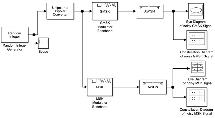
Figure 3.1: Simulink model for comparison between MSK and GMSK
3.2.Functional blocks of the Simulink model
- Random integer generator block
To generate random integer-valued data which is uniformly distributed in the range of 0 to M-1, a random integer generator. M is the size of the constellation of the MSK or GMSK signal and is specified by the “set size” parameter (www.mathworks.com, 2020).
- Unipolar-to-Bipolar Conversion block
This block is used to map the input (unipolar) signal to output signal which are bipolar. The input is the randomly generated integer-valued data from the random integer block and is in the range of between 0 and M-1. The value of M is set under the “M-ary number” parameter. In this case M=2. The bipolar output signal is constituted by integers in the range of [-(M-1), M-1]. It is noted that for even M values, odd output number are produced and for odd M, even output numbers are generated (Sachchidanand Shukla, 2017).
- GMSK-modulator baseband
By employing the Gaussian minimum shift keying modulation scheme, the GMSK Modulator modulates the output of the unipolar to bipolar converter block to produce a modulated signal in baseband representation (Prameela and Pravin, 2015). Under the “BT product” parameter, we can change the value of the product of the bandwidth and time and the resulting value has to be a positive scalar. BT product parameter is useful in reducing the bandwidth while increasing inter-symbol (inter-channel) interference. The BT product used in this case is 0.6.
Through the “Pulse length” parameter, the Gaussian pulse shape length is measured in symbol intervals. From this parameter, a phase shift of π/2 radians results from an input symbol of one (1) (www.mathworks.com, 2020).
- MSK modulator baseband block
The differential encoder is used in the MSK Modulator block to modulate the signal from the unipolar to bipolar converter block using minimum shift keying modulation scheme to produce a modulated signal in baseband representation. The input signal to this block can be a column vector or a scalar-valued input. The “Samples per symbol” parameter is useful when a column vector input signal is detected. The output signal width is obtained from the product of the “samples per symbol” parameter and the number of symbols (www.mathworks.com, 2020).
Pulse shape filtering is used in the differential encoder of the MSK modulator for smoothing the modulated signal’s phase transitions. The frequency pulse shape is given by the following piecewise defined function
Where LT is the pulse duration and lso represents the length of pulse in symbols intervals.
The phase response function q(t) is got from the frequency pulse, g(t), through this relation:
- AWGN Channel block
This block is used for the addition of the input signal and the white Gaussian. The sample time of The AWGN Channel block is inherited from the input signal. In this block, we set the signal to noise ratio (SNR) to 21 dB (Prameela and Pravin, 2015)
- Eye diagrams block
An eye diagram is used in digital communications to analyze the impact of noise on system performance through visual indication. Multiple traces of the modulated signal are displayed in the Eye Diagram. Modulation characteristics of the modulated signal are revealed using the eye diagram block and the effects of channel distortions and pulse shaping can be observed appropriately. The eye diagram block displays the IQ plane with both real and complex-valued floating signals (Prameela and Pravin, 2015).
- Constellation diagrams block
This modulator block is used to visualize the modulated signal constellation and to provide the capability of visual indication directly from the block mask. The constellation diagram block displays the IQ plane with both real and complex-valued floating signals. Quantitative and qualitative analysis can be done on modulated signal from the results of the constellation diagrams (Kamilo Feher, 2015).
4. RESULTS AND DISCUSSION
The differences between the GMSK and MSK modulation schemes are illustrated using the constellation diagrams and eye diagrams of the noisy MSK and GMSK signals. The SNR was set to 21 dB in the AWGN channel block and the BT product set at 0.6 in the GMSK modulator block. The following figures shown the differences in the eye diagrams and constellation diagrams of GMSK and MSK for pulse length of 3.
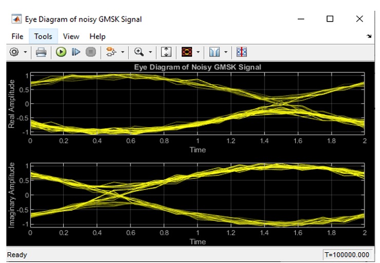
Figure 4.1: Eye Diagram of Noisy GMSK Signal (SNR = 21 dB, BT = 0.6)
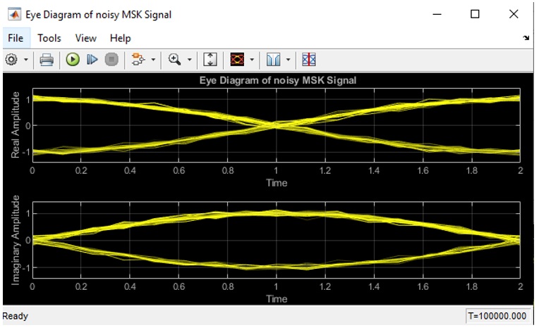
Figure 4.2: Eye Diagram of Noisy MSK Signal (SNR = 21dB)
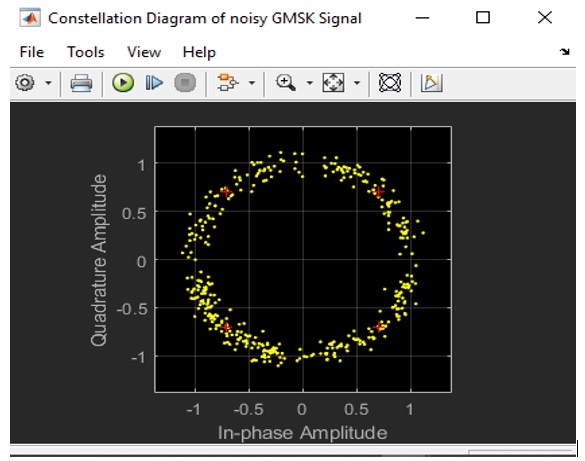
Figure 4.3: Constellation Diagram of Noisy GMSK Signal (SNR = 21 dB, BT = 0.6)
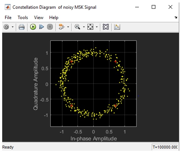
Figure 4.4: Constellation Diagram of Noisy MSK Signal (SNR = 21 dB)
From the eye-diagrams and constellation diagrams above, it is clear that GMSK has an advantage over MSK in terms of spectral efficiency. The MSK scheme has inward side-lobes which GMSK lacks hence GMSK has better spectral properties. GMSK has more extending sidebands than MSK thus causing more noise in the adjacent channels.
Varying the BT product affects the bandwidth of the pre-modulation Gaussian filter in GMSK hence a compact power spectrum is achieved via pulse-shaping. The higher the BT product the smaller the bandwidth and vice versa. However, this introduces more inherent inter-symbol interferences. It was also noted that at very high BT product values, there is little difference between MSK and GMSK modulated signals.
Increasing the signal to noise ratio introduced more noise in both the MSK and GMSK modulation schemes.
- CONCLUSION
In a nutshell, when conservation of bandwidth and amplitude saturating transmitters are of importance in digital links, GMSK and MSK modulation techniques are used. . The comparison between GMSK and MSK through eye diagrams and constellation diagrams illustrated that MSK has a constant envelope and does not introduce any inter-symbol interferences while the GMSK is more compact but with severe inter-symbol interferences. Increasing the BT product reduced the bandwidth while increasing SNR increased the noise in the adjacent channels due to increased inter-symbol interferences.
The MSK and GMSK comparison was developed in SIMULINK and different modulation characteristics analyzed successfully.
Resources
- 24 x 7 Availability.
- Trained and Certified Experts.
- Deadline Guaranteed.
- Plagiarism Free.
- Privacy Guaranteed.
- Free download.
- Online help for all project.
- Homework Help Services
