Deployment Diagram Homework Help
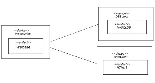
The UML diagram which models the physical deployment diagram of artifacts on nodes is known as deployment diagram. The nodes in the diagrams are appear as boxes and the artifacts are allocated to each node appears as rectangular box in all the nodes. Notes can have sub notes, which appears as nested nodes.
There are two types of node in deployment diagrams:
- Device Node
- Execution Environment Node
The device nodes in component diagrams are the physical computing resources with processing memory and services to execute software like mobile phones etc. And the execution environment node is a computing resource that runs within an outer node.

Purpose Of deployment diagram:
The deployment diagram are used to visualize the topology of the physical component of the system in which software are deployed.
Component diagrams are used to describe the components and deployment diagrams shows how they are deployed in hardware.
By the help of component diagram we can describe runtime processing nodes.

If you need homework, assignment, coursework help in Deployment Diagram contact our online chat support.

